Instruction Manual mErcury SrS
Dear customer, We are delighted that you have decided to purchase the PowerBox Mercury SRS power supply from our range. We hope you have many hours of pleasure and great success with your PowerBox Mercury SRS. Product description The PowerBox Mercury SRS is a new power management system which combines all the experience and findings we have gained over the last few years, together with customer requests, in a single compact unit.
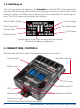
1.1. Installing the Mercury SRS in the model The Mercury SRS must be screwed to a hard surface in the model, otherwise it is possible that the integral iGyro will not work properly. If the mounting plate is large, it must be stiffened by the addition of cross-struts. Please note that the Mercury SRS must always be installed in the model at right-angles to the fuselage centreline.
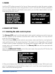
1.3. Switching on This is the procedure for switching the PowerBox on: hold the SET button pressed in, and wait until the orange LED on the switch lights up. Continue to hold the SET button pressed in while you briefly press buttons I and II; this completes the switching process.
3. MENU Hold the SET button pressed in for two or three seconds to enter the menu system; you can now move the cursor using buttons I and II. Hold the SET button pressed in once you have selected a particular menu point; you can then adjust values and settings using buttons I and II. 4. BASIC SETTINGS 4.1. Selecting the radio control system The Mercury SRS must be informed which radio control system you wish to use, as the bus systems of the various manufacturers differ very widely.
- PowerBox P²BUS Connect a receiver to the P²BUS output on RX1 and RX2. - Futaba FASST and FASSTEST The Mercury SRS works with the S-BUS signal. Many receivers require one output to be re-assigned to S-BUS: • R7003SB: no adjustment necessary; signal present at “PORT 1”. • R7008SB: output 8 must be set to S-BUS, Mode B or Mode D. • R6303SB: no adjustment necessary; direct S-BUS output fitted • R6308SB(T): output 8 must be set to S-BUS, Mode B or Mode D.
Telemetry: if you wish your transmitter to receive telemetry data, connect the TELE output of the PowerBox to the EXT input of your satellite. - Graupner HoTT When a HoTT system is used, the receivers should first be bound; adjustments can then be carried out in the Telemetry menu. All receivers require the CH-OUT-TYPE to be set to SUMD-OF-16. • SUMD-OF-16 is present at Output 8. • GR32: SUMD-OF-16 is present at Output S.
4.3. Battery type The battery type you wish to use is also determined in the GENERAL SETTINGS menu. This setting is important, otherwise the battery display will not be correct. 4.4. Output voltage This is where you set your preferred output voltage: the available options are a regulated output voltage of either 5.9V or 7.4V. If you intend to use the 7.4V option, please ensure that all servos, switches and valves connected to the system are HV types, as the voltage is the same at all outputs. 5.
correct axis. Hold the model’s tail at a slight angle, so that the bar deflects fully to the right, and wait until the elevator jumps back to the neutral position. The screen now switches automatically to the next display. 2. At this point you are requested to swing the model’s tail to left or right: the rudder should immediately deflect in response to this movement.
Explanation of terms: DS 1 – 5: VT: Door sequencer Vector thrust: thrust vector control The two model types Normal+VT and Delta+VT include a special feature as standard: in both cases the VT-RUDDER and VT-ELEVATOR outputs are switched off in flight modes 1 and 2. This allows you to control a jet with thrust vector control using only three channels, without having to set up mixers at the transmitter.
Note: for model types with VT (Vector Thrust) it is only possible to engage vector control in Flight Mode 3. If you subsequently decide that the model needs more complex mixers, select a model without VT (Normal or Delta) and make use of the vector function at the transmitter. 5.3. Flight mode switch Assign a three-position switch of your choice at the transmitter, and check that the travel is set to -100% to 0% to +100%.
5.5. Flight mode configuration The next stage is to define the gyro function required for each flight mode. This setting defines the task which the iGyro is to carry out in flight modes 1, 2 and 3. Note that in flight mode 1 the Assistant only permits the functions OFF or RATE MODE. Important point concerning the Flight Mode settings which are pre-defined in the Assistant: these can be altered at any time in the Gyro Settings menu.
- ATT ASSIST ALL: This setting is identical to the above option, except that attitude maintenance is also active on rudder. This makes it easy to fly slow rolls, as the rudder automatically maintains the correct attitude. However, this flight mode option must not be used for normal flying, as the rudder would then try to maintain heading through aileron turns, making the model reluctant to turn.
5.6. Teaching the aileron, elevator, rudder, landing flap and throttle functions During the following sequence of queries the Assistant assigns the channels to the appropriate functions as they arrive from the transmitter. The left-hand column shows the detected channel; in the centre is the function; the right-hand column shows the associated output of the Mercury SRS. You can immediately plug in your servos and check their operation.
This completes the Setup Assistant procedure. In the following stage all the remaining functions, such as retract system, brakes and lighting, are assigned and adjusted where necessary using the servo-matching function. 6. OUTPUT MAPPING Since the Setup Assistant does not cover all the functions, Output Mapping is employed to assign additional functions to the outputs; it is also possible to shift existing functions to other outputs.
- DOORS. 1 to 5: If you select one of these functions, the appropriate output is linked to the door sequencer. Which wheel door or valve is controlled by which door sequencer output is left entirely up to you, but we recommend using the Door Sequencer Assistant for the set-up process, as this will assign the outputs correctly. HD/FS: - FS (Failsafe): If a complete loss of signal occurs, affecting all receivers connected to the system, this output moves to a previously determined position.
Select SERVO-MATCHING in the Main menu, and the following screen display appears: To ensure accurate servo matching, the output to be adjusted must first be initialised. Leave the associated transmitter stick at centre. Move the cursor to INIT OUTPUT and press the SET button. Now move the transmitter stick to both end-points. The graphic display shows the movement of the upper arrow, which indicates the input signal. The bar inside the box shows the movement of the output.
- You can now release the aileron stick: the PowerBox maintains this position. You now have both hands free, and can adjust the position accurately with one hand, using buttons I and II, whilst checking the length (matching) of the disconnected ball-link at the horn with the other hand. - Press the SET button again to conclude this adjustment. - Complete the set-up procedure for the centre position and both end-points before re-connecting the servo linkage.
-M ove the transmitter switch to the “flaps extended” position, then press the SET button again. -N ow set the appropriate end-point using button I or II before concluding the procedure with the SET button. -M ove the transmitter switch to the “retracted” position, then press the SET button again. -N ow set the corresponding end-point with button I or II, and conclude the procedure by pressing the SET button. -B oth landing flaps will now move synchronously. 8.
Access the PowerBox’s Door Sequencer menu, and select the SETUP ASSISTANT point. You will now see the following screen display: Operate the appropriate transmitter switch, and the PowerBox automatically detects it as the switch which you have assigned to the retract system. The on-screen arrows should now be located in front of UP/DOWN. If you find that your retract switch works in the wrong “sense” (direction), correct it by reversing that output at the transmitter. Press the SET button again to proceed.
Retract undercarriage: Close nosewheel doors Retract nosewheel retract main undercarriage Open main wheel doors close main wheel doors Mode 3: Extend undercarriage: Open nosewheel doors Open main wheel doors extend nosewheel close nosewheel doors extend main undercarriage close main wheel doors Retract undercarriage: Open nosewheel doors Open main wheel doors retract nosewheel close nosewheel doors retract main undercarriage close main wheel doors Move the cursor to the appropriate mode, and press the
The undercarriage should now retract. If not, hold button I pressed in until the valve is triggered, and the undercarriage retracts. Press the SET button to move on to the next stage of the procedure: Connect the servo for the first nosewheel door to output F. Use the SET button to close the first nosewheel door, then confirm by pressing the SET button. In the next screen display open the first nosewheel door again. The next steps are used to set up the second nosewheel door and the two rear wheel doors.
9. TEST FLY ASSISTENT Once you have completed all the points listed above, it is time to carry out test-flights with the iGyro. Even though the Mercury version of the iGyro only requires one rotary knob or slider for the adjustment process, we recommend carrying out the procedure on the ground several times until you are confident that you know how to complete the process. Note that previous settings are overwritten every time you carry out this point.
Launch the model and fly at half-throttle parallel with the landing strip. Increase gyro gain until the aircraft just starts to oscillate around one axis. At this point reduce gain slightly until the model shows no sign of oscillating in any speed range. Note: if you are using the Mercury SRS without GPS II, it is vital to ensure that the gain you set does not allow the model to oscillate even at full-throttle.
FM3: TORQUE ROLL Aileron: 100% ATT.ASSIST: on Elevator: 100% ATT.ASSIST: on Rudder: 100% ATT.ASSIST: on The model’s set-up is now complete, although manual fine adjustment is still possible at any time: either by manual intervention in Gyro Settings, or by assigning a Gain channel for individual axes. The latter enables you to fine-tune individual axes accurately in the air. 10. ADDITIONAL FUNCTIONS AND SET-UP FACILITIES 10.1.
10.3. Gyro Settings The Gyro Settings menu permits you to adjust the gyro values manually. We recommend that you set up the iGyro using the Setup Assistant and test-fly the model using the Testfly Assistant; in the majority of cases it is likely that no further fine-tuning will be required. However, the following section describes the individual points in case you ever need to adopt non-standard settings. - AXIS: at this point you select the axis which is to be adjusted.
- AIRSPEED FACTOR: after the gyro test-flight the airspeed factor defaults to a value of 3. If you subsequently discover that the model starts to oscillate at high speed, but behaves perfectly at low speed, then you need to increase the airspeed factor. The higher the airspeed factor, the lower the gyro gain as the model’s airspeed increases. 10.4.
A single Task contains the following information: Value Range Task number 1 - 12 Extend or retract undercarriage UP » DOWN / DOWN » UP Servo number 1–6 Servo START position 700µs – 2300µs Servo STOP position 700µs – 2300µs Start time 0 – 25.0s Stop time 0 – 25.0s Here is an example which demonstrates how the system works: UP » DOWN: all the tasks which you set up with this direction are carried out when the retract switch on the transmitter is moved to the “Extend” position.
The positional values vary according to your linkages, and must therefore be set individually to suit the specific model. It is important to ensure that the wheel doors do not jam mechanically. The times stated in our example are also just an illustration, and need to be set to suit your preference. The timing of the tasks does not need to coincide with the task numbering. For example: it is permissible for Task 5 to occur before Task 2. Our example clearly shows how the function is built up.
10.5. Input Mapping Modern SRS bus technology makes it possible to assign channels for particular functions without restriction. The quickest method of assigning the Input Mapping functions is to use the Setup Assistant, but it is also possible to assign them manually at this point. Since V07 this facility also includes Gain channels for adjusting the gain of the individual gyro axes.
- SET ORIENTATION: this is the point where the installed position of the Mercury SRS in the model is established. As in the Setup Assistant, all you have to do after selecting this menu point is raise or lower the model’s tail. The on-screen bar shows when the angle of tilt is sufficient. Once the bar has filled to the right, you need to hold the model motionless; the process ends automatically once the PowerBox has unambiguously detected the unit’s installed orientation.
b) Using the USB Interface Adapter (9020), a PC and the PowerBox Terminal program. The PowerBox Terminal software is available as a free download from our website. Connect the BlueCom Adapter or the USB Interface Adapter to the Tele-Input. 11. SPECIFICATION Operating Voltage: 4,0V - 9,0V Battery type: 2s LiPo/LiIon, 2s LiFePo, 5s NiMH/NiCd Current drain (ON): approx. 99mA Current drain (OFF): approx. 3µA Output voltage regulated: 5,9V and/or 7,4V Max.
12. DIMENSIONS www.powerbox-systems.
13. SET CONTENTS - PowerBox Mercury SRS - OLED-Display - SensorSwitch - 3 Patchwires 3-pole, 200mm - 8 mounting screws - Operating instructions Optional: GPS Sensor 14. SERVICE NOTE We make every effort to provide a good service to our customers, and have now established a Support Forum which covers all queries relating to our products. This helps us considerably, as we no longer have to answer frequently asked questions again and again.
The guarantee does not cover damage caused by incorrect usage, e.g. reverse polarity, excessive vibration, excessive voltage, damp, fuel, and short-circuits. The same applies to defects due to severe wear. We accept no liability for transit damage or loss of your shipment.
12/2020 PowerBox-Systems GmbH Ludwig-Auer-Straße 5 D-86609 Donauwoerth Germany +49-906-99 99 9-200 +49-906-99 99 9-209 www.powerbox-systems.