
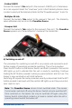
User manual PowerBox Source


4
PowerBox-Systems − World Leaders in RC Power Supply Systems
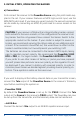
2. INITIAL STEPS, OPERATING THE BACKER
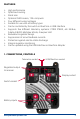
a) Connections
First connect the receiver to the PowerBox Source using the patch leads sup-
plied in the set. If your receiver features an MPX high-current input, use the
MPX/MPX patch lead. If you have any vacant sockets, the second connection
can be made by connecting an MPX/JR patch lead to a servo socket on the
receiver.
CAUTION: If your receiver is tted with an integral battery backer, connect
both sockets to the servo sockets; in this conguration the receiver’s bat-
tery backer function is bypassed. Now connect the Sensor Switch to the
appropriate socket on the backer. If your model is subject to severe vi-
bration, we recommend securing the ribbon cable at one additional point
at least. If the connector should fall out, this would have no effect on the
backer’s switched state, but it would prevent you switching it off.
The batteries can now be connected to the backer’s MPX inputs, taking
care to maintain correct polarity. We recommend the PowerPak 2.5X2
ECO or PRO, or - for larger models - the PowerPak 5.0X2 ECO or PRO.
If you prefer to use other makes of battery, or packs you have prepared
yourself, please take particular care over polarity, as the regulator ICs will
be destroyed if you connect a battery with reversed polarity. In order to
minimise power losses we decided against providing reverse polarity pro-
tection. The + symbol is visible on the case cover.
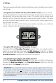
If you wish to display all the battery-relevant data on your transmitter screen,
connect the Tele output of the PowerBox Source to the receiver’s Telemetry
input before switching the system on.
- PowerBox CORE
By default the PowerBox Source is set up for the P²BUS. Connect the Tele
output on the Source to the receiver’s P²BUS socket. The PowerBox can now
be set up from the transmitter, and the telemetry data can be transferred.
- Jeti EX-Bus
Connect the backer’s Tele output to an EX-BUS capable receiver input.