VERTICAL STORING DOCKLEVELER INSTALLATION & OPERATION MANUAL Job Number Job Name Serial Numbers POWERAMP P.O.
Table of Contents Safety ....................................................................................................... 1 Safety Alert Symbols ............................................................................ 1 General Safety Precautions ................................................................. 1 Introduction................................................................................................ 2 Installation ..............................................................
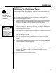
Safety Safety Alert Symbols WARNING This Safety Alert Symbol Means ATTENTION is Involved! The Safety Alert Symbol identifies important safety messages on equipment, safety signs, in manuals, or elsewhere. When you see this symbol, be alert to the possibility of personal injury or death. Follow the instructions in the safety message.
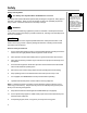
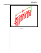
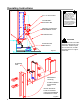
Introduction LIP PLATFORM FRAME Figure 1 2
Introduction This manual covers the hydraulic VS dockleveler manufactured by Poweramp. It has been equipped with a double acting hydraulic hoist cylinder to control the raising and lowering of the platform. Operation of the unit is via constant pressure push buttons located in a control enclosure. It is the intent of Poweramp that the control enclosure be located above the loading dock floor and on the loading dock side of the VS dockleveler.
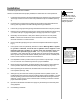
Installation persons or property. Installation VS Dockleveler Frame WARNING Secure anchoring of the vertical storing dockleveler frame is essential for safe operation. Inspect all existing curb steel prior to installation. The following installation procedure has been developed to guide you. Unauthorized modifications or alterations made to any of the parts or assemblies on this product may affect its warranty and overall performance.
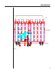
Installation A B A C Figure 3 A.
Installation Vertical Storing Dockleveler Installation With the VS dockleveler frame properly installed, the dockleveler can now be positioned. 6 1. Poweramp VS docklevelers are shipped with lifting lugs attached to the outboard joists. These lugs must be moved to the 3/4" hole provided in the lip for installation (See Fig. 3). 2. Lift platform into vertical position by lifting lugs and position VS leveler platform with three (3) rear hinge tubes in line with matching frame hinge weldments. 3.
Operating Instructions WARNING Always operate the VS dockleveler from atop the loading dock. Never stand or work under the VS dockleveler unless it is securely supported. Use safe work habits. Controls Poweramp VS docklevelers are operated via a remote mounted control enclosure. This enclosure has a Nema 12 rating. Included is a toggle switch to turn 115 volt control voltage on and off. Also included are three push buttons which require constant pressure to operate the dockleveler.
Operating Instructions WARNING 1/2" x 1/2" FILLER BAR LOCKING BOLT STORAGE TUBE WHEN A HYDRAULIC CYLINDER IS EXTENDED, IT MUST BE FULL OF HYDRAULIC FLUID TO SUPPORT A LOAD. EXTENDING HYDRAULIC CYLINDERS BY A MEANS OTHER THAN HYDRAULIC POWER CAN RESULT IN SEVERE PERSONAL INJURY OR DEATH.
Preventive Maintenance WARNING WHEN A HYDRAULIC CYLINDER IS EXTENDED, IT MUST BE FULL OF HYDRAULIC FLUID TO SUPPORT A LOAD. EXTENDING HYDRAULIC CYLINDERS BY A MEANS OTHER THAN HYDRAULIC POWER CAN RESULT IN SEVERE PERSONAL INJURY OR DEATH. Servicing the VS dockleveler With proper care, your Poweramp VS dockleveler will provide many years of satisfactory service.
Preventive Maintenance B WARNING A Arrow on flow control valve must point away from hoist cylinder. Improper installation will allow the leveler to free fall which could result in serious injury and or property damage. WARNING C A B C D E 11 Lip Hinge Line Lip Cylinder Pin Storage Prop (3 Places) Hoist Cylinder Pins (2) Rear Hinge Pins (3) D E Figure 6 WHEN A HYDRAULIC CYLINDER IS EXTENDED, IT MUST BE FULL OF HYDRAULIC FLUID TO SUPPORT A LOAD.
Preventive Maintenance Breather cap near deck, fill plug near viewer Oil level indicator plug Pressure relief screw Figure 7 12
Troubleshooting Guide WARNING Always engage prop locks when working under or in front of the VS leveler. Always barricade the work area to prevent unauthorized use of the unit during repair or maintenance procedures. Always lock out all electrical disconnects after raising platform and setting maintenance lock(s) when service under the unit is required. More than one electrical disconnect switch may be required to de-energize the equipment.
Troubleshooting Guide Problem The VS dockleveler does not operate. Motor energizes but does not run (motor hums, overload device should trip). Solution(s) Cause(s) 1. 3 phase units only--voltage at one line is absent (motor being single phased). 1A. Fuses at motor branch circuit overcurrent device only--check for tripped fuse. Replace fuse. Determine cause of fuse tripping. 1B. Check motor starter for component failure. Disconnect wires at load side of starter.
Troubleshooting Guide Problem Cause (s) Solution (s) The VS dockleveler motor runs continu- 1. 1 phase unit only--contractor ously stuck on. 1. Locate and replace. The VS dockleveler shuts off before prop is fully engaged 1. Prop limit switch misadjusted 1. Adjust (fig. 4) so that switch activates when prop is fully extended. The VS dockleveler will not lower. 1. Locking device in place. 1. Reposition locks in unlock position (See figs 4 & 5). 2. Lowering speed control shut off. 2.
VS Dockleveler Parts List 3 8 & 8b 9 ITEM 1 2 3 4 5 6 7 8 8b 8c 9 10 11 10 1 11 DESCRIPTION Lip Cylinder Pin Lip Cylinder Reservoir Down Speed Valve Hoist Cylinder Pin (Rear Hinge) Hoist Cylinder Pin Motor 1P Motor 3P Pump Hydraulic Filter Solenoid-Prop Kicker Storage Prop Assembly 2 7 5 4 6 PART NUMBER 0522-0005 0525-0085 9304-0008 8581-0091 0525-0066 9202-0040 9202-0039 3411-0008 3411-0019 9301-0132 9301-0121 8581-0023 9225-0016 16
Valve Parts List 3 2 4 6 1 ITEM 1 2 3 4 5 6 17 DESCRIPTION Complete Valve Assembly 3 way valve Coil Assembly 2 way valve NC 2 way valve NC 4 way valve 5 PART NUMBER 8585-0080 8581-0005 8583-0032 8581-0010 8581-0102 8581-0011
Visual Inspection Poweramp's hydraulic VS dockleveler has been designed to make loading or unloading trailers easier. Sections of this manual have been devoted to installation, operation, maintenance, etc. To assure that your VS dockleveler stays in top working order, visual inspections should be made monthly. These inspections should include the VS dockleveler assembly and the curb steel. The curb steel acts as the support anchor for the pivoting end of the VS dockleveler.
SYSTEMS, INC. WARRANTY Vertical Storing Dock Leveler Systems, Inc. guarantees the materials, components and workmanship in your Poweramp dock leveler to be of the highest quality and to be free of defects in material and workmanship for a period of five (5) years from date of shipment. Systems, Inc. further guarantees the hydraulic components on all Poweramps for a period of five (5) years from date of shipment.