VS SERIES Dock Leveler Owner’s Manual POWERAMP • Division of Systems, Inc. • W194 N11481 McCormick Drive • Germantown, WI 53022 800.643.5424 • fax: 262.257.7399 • www.docksystemsinc.com • techservices@docksystemsinc.com Printed in U.S.A. Copyright © 2008 Manual No.
Table of Contents Page Safety Recognize Safety Information . . . . . . . . . . . . . . . . . . . . . . . . . . . . . . . General Operational Safety Precautions . . . . . . . . . . . . . . . . . . . . . . Operational Safety Precautions . . . . . . . . . . . . . . . . . . . . . . . . . . . . . Maintenance Safety Precautions . . . . . . . . . . . . . . . . . . . . . . . . . . . . Safety Decals . . . . . . . . . . . . . . . . . . . . . . . . . . . . . . . . . . . . . . . . . . . .
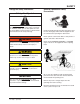
SAFETY Recognize Safety Information General Operational Safety Precautions Safety-Alert Symbol The Safety-Alert Symbol identifies important safety messages on equipment, safety signs, in manuals, or elsewhere. When you see this symbol, be alert to the possibility of personal injury or death. Follow the instructions in the safety message. Read and understand the operating instructions and become thoroughly familiar with the equipment and its controls before operating the dock leveler.
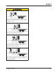
SAFETY Operational Safety Precautions Learn the safe way to operate this equipment. Read and understand the manufacturer's instructions. If you have any questions, ask your supervisor. Stay clear of dock leveling device when freight carrier is entering or leaving area. Chock/restrain all freight carriers. Never remove the wheel chocks until loading or unloading is finished and truck driver has been given permission to drive away.
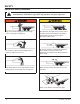
SAFETY Do not use dock leveling device if freight carrier is too high or too low. Do not overload the dock leveling device. Do not operate any equipment while under the influence of alcohol or drugs. Do not leave equipment or material unattended on dock leveling device.
SAFETY Maintenance Safety Precautions ALWAYS stand clear of dock leveler and lip when working in front of the dock leveler. Failure to do this may result in serious personal injury or death. ALWAYS disconnect electrical power source and ground wire before welding on dock leveler. Hydraulic and electrical power must be OFF when servicing the equipment. For maximum protection, use an OSHA approved locking device to lock out all power sources.
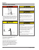
SAFETY Safety Decals Safety Decal on Rear Platform Safety Decal on Leveler Frame Safety Decal on Platform Cylinder Safety Decal on Rear Platform 4111-0008 — April 2008 5
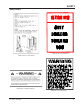
INTRODUCTION General Information Dock Leveler Stock Specifications Models VS-65 VS-66 VS-68 VS-655 VS-656 VS-658 VS-75 VS-76 VS-78 Nominal Size W x L 6’ x 5’ 6’ x 6’ 6’ x 8’ 6’6” x 5’ 6’6” x 6’ 6’6” x 8’ 7’ x 5’ 7’ x 6’ 7’ x 8’ VS dock levelers are available in the following sizes, weight capacities, and options: Congratulations on your choice of a Poweramp Vertical Storing dock leveler. This manual covers the VS (Vertical Storing) series hydraulic dock leveler.
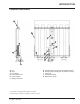
INTRODUCTION Component Identification A B C D E K I F G H G J A. B. C. D. E. F. Lip Deck Lip Cylinder Flow Control Valve Hoist Cylinder* Storage Prop Yoke G. H. I. J. K. Trombetta Valve-Prop Kicker (Behind Prop Assy) Storage Prop Assembly with Lock-Out Pin incl (F) Hinge Pin Stored Limit Switch Maintenance Props * Some models are equipped with multiple hoist cylinders. *Powerpack may be mounted on underside of leveler or remotely.
INSTALLATION Prepare Pit A B C D C A B A—Distance (Pit Width) (Front and Rear) B— Distance (Dock Floor-to-Pit Floor) (All Four Corners) 1/2” Taper Rear to Front C— Distance (Pit Length) (Both Sides of Pit) D— Distance (Pit Corner-to-Corner) (Top, Bottom, and Both Sides) Before lowering the dock leveler into the pit, the following must be performed: Post safety warnings and barricade the work area at dock level and ground level to prevent unauthorized use of the dock leveler before installation has bee
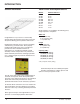
INSTALLATION Prepare Dock Leveler A B A— Lifting Bracket The dock leveler is heavy. Use a lifting device and chains with the appropriate lifting capacity and reach. Always use the lifting brackets provided with the unit whenever lowering or lifting a dock leveler into or out of a pit. Failure to follow these instructions may result in damage to dock leveler and/or serious personal injury or death.
INSTALLATION IMPORTANT Installation of VS levelers from inside is recommended due to combined height of leveler and proper lifting equipment may be greater than outside door height. 1. Remove any control panel, bumpers or palletizing that may be banded to the frame of the dock leveler. Do not remove banding on hoist cylinder or storage prop at this time. 2. Make sure the mounting hardware of lifting bracket(s) (A) is snug. The brackets should pivot relatively freely on the mounting cap screw.
INSTALLATION Install Dock Leveler Shim Stacking Methods E F G H I B C IMPORTANT The minimum size of the shim that contacts the leveler frame (i.e., the top shim of each shim stack) must be at least 4-1/2 x 4-1/2 in. (114.3 x 114.3 mm) to support the full width of the hoist cylinder / storage prop weldment. Use the thickest shim stock possible for stability and weld penetration purposes. DO NOT use multiple layers of 1/8 in. (3.18 mm) or thinner shim stock. D 5.
INSTALLATION The dock leveler is heavy. Use chains and a lifting device with the appropriate lifting capacity and reach. Failure to do so may result in damage to dock leveler and/or serious personal injury or death. E B C C F D A A— Rear Imbed B— Dock Leveler C— Maintenance Props D— Hinge Pins 6. Lube the three rear hinge pins using grease Install the three pins in the rear imbed only through out the first hinge tube. E— lifting Lug F— Storage Prop 8.
INSTALLATION Install Control Panel and Wiring A The electrical power must be OFF prior to electrical installation. For maximum protection, use an OSHA approved locking device to lock out all power sources. Only the person installing the equipment should have the key to unlock the power source. B C Failure to follow these instructions may result in serious personal injury or death. DO NOT make any final electrical connections until all welding has been completed.
INSTALLATION Purging air from the VS hydraulic system. DO NOT grind or weld if hydraulic fluid or other flammable liquid is present on the surface to be ground or welded. DO NOT grind or weld if uncontained hydraulic fluid or other flammable liquid is present. Stray sparks can ignite spills or leaks near the work area. Always clean up the oil leaks and spills before proceeding with grinding or welding. Always keep a fire extinguisher of the proper type nearby when grinding or welding.
INSTALLATION Put New Dock Leveler Into Service 1. Disconnect the external lifting device and chains from the lifting brackets. 2. Complete all welding. 3. Install hydraulic hoses and fill system. 4. Connect all electrical connections. 5. Purge System(see Purging pg 14). 4 Test leveler for operation. Always stand clear of platform lip when working in front of the dock leveler. Serious personal injury or death may result. Rod Eye adjustment & New installation. 1.
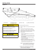
OPERATION Theory A J K B K G L C M A — Control Box B — Platform C — PowerPack L D — Hoist Cylinder F — Dual-Lanyard Pull Ring G — Reservoir When a button is pushed on the control panel this activates an electric motor (C) which, drives a hydraulic pump. The hydraulic pump forces oil into the platform cylinder(s) (D), causing the platform to rise or lower. Releasing the button will stop the platform from moving (except in the float mode).
OPERATION Operating Instructions Stay clear of dock leveler when freight carrier is entering or leaving dock area. DO NOT move or use the dock leveler if anyone is under or in front of leveler. 12 in. (305 mm) 12 in. (305 mm) Keep hands and feet clear of pinch points. Avoid putting any part of your body near moving parts. Failure to follow these instructions may result in severe personal injury or death. Only trained personnel should operate the dock leveler.
OPERATION Operating Instructions—Continued Ramp Loading/Unloading Instructions NOTE: If end unloading is required, see End Loading/Unloading Instructions on page 19. 1. Check to make sure truck/trailer is positioned squarely against dock bumpers. 2. Instruct driver to remain at the dock until the loading or unloading process has been completed. 3. Chock the truck/trailer wheels or use the truck restraint if available. 5. Proceed with loading or unloading the truck/trailer. 6.
OPERATION Operating Instructions—Continued Below Dock End Loading/Unloading Instructions Dock Leveler Loading/Unloading Instructions 1. Check to make sure truck/trailer is positioned squarely against dock bumpers. 2. Instruct driver to remain at the dock until the loading or unloading process has been completed. 3. Chock the truck/trailer wheels or use the truck restraint if available. 4. Lower platform and lower the lip.
MAINTENANCE Service Dock Leveler Safely A B C A— Tagout Device B — Lockout Device C —SAFETY legs When service under the dock leveler is required, always lock all electrical disconnects in the OFF position after raising the platform and engaging the maintenance prop. Failure to do this may result in serious personal injury or death. Always stand clear of the dock leveler lip when working in front of the dock leveler.
MAINTENANCE Periodic Maintenance E A E D C B A— Lip Hinge Area B— platform Pins C— Storage Prop D— Hoist Cylinder Before performing any maintenance under the dock leveler, lock the electrical power source in OFF position and lock the maintenance prop in the service position using an approved locking device. (See Service Dock Leveler Safely in this section.) Failure to follow these instructions may result in serious personal injury or death.
MAINTENANCE Q Regular maintenance must be performed on a weekly and quarterly schedule. N P Weekly Maintenance • Operate the dock leveler through the complete operating cycle to maintain lubrication. NOTE: Make sure the limit switch is clear of debris. M Pressure • Inspect the platform hinge and the lip hinge areas. The hinge areas must be kept free of dirt and debris. Build-up of foreign material in the hinge areas will cause abnormal operation.
ADJUSTMENTS SC Adjust Main Pressure Relief When service under the dock leveler is required, always lock all electrical disconnects in the OFF position after raising the platform and engaging the maintenance prop. Failure to do this may result in serious personal injury or death. A Always post safety warnings and barricade the work area at dock level and ground level to prevent unauthorized use of the dock leveler before maintenance is complete.
ADJUSTMENTS Adjust Main Pressure Relief Remote Mount F E When service under the dock leveler is required, always lock all electrical disconnects in the OFF position after raising the platform and engaging the maintenance prop. Failure to do this may result in serious personal injury or death. D A Always post safety warnings and barricade the work area at dock level and ground level to prevent unauthorized use of the dock leveler before maintenance is complete.
ADJUSTMENTS Stored Limit Switch Adjustment 1. Loosen Set Screw 2. With roller arm contacting storage prop, rotate adjustment screw counter clockwise until a “Click” noise is heard. 3.Tighten set screw head cap screw. 4. Readjust as needed to leveler allow to store 3 to 5 deg from vertical. 5. After adjusting the stored limit switch check for correct play in the prop. Adjustment Screw Set Screw Down Speed Control Adjustment If the dock leveler lowers to slow, the down speed control, requires adjustment.
ADJUSTMENTS Maintenance Prop Adjustment Maintenance Prop Adjustments 1. Raise platform fully and engage the maintenance prop in the service position (If dock leveler has not been used recently cycle leveler once). 2. Turn OFF all electrical power to the dock leveler. Attach safety lockout and tagout devices. 1” 3. Adjust yoke on maintenance till you have min. 1“ of free play in the prop”. 4. When the play in the prop is correct only 1-1/2 threads max will be exposed through the yoke.
TROUBLESHOOTING Troubleshooting When service under the dock leveler is required, always lock all electrical disconnects in the OFF position after raising the platform and engaging the maintenance prop. Failure to do this may result in serious personal injury or death. Always post safety warnings and barricade the work area at dock level and ground level to prevent unauthorized use of the dock leveler before maintenance is complete. Failure to do this may result in serious personal injury or death.
TROUBLESHOOTING Symptom Possible Cause Platform does not rise. Motor overload device Motor does not energize. tripped or fuse blown. Solution Reset overload relay (three-phase) or replace fuse(s) (single-phase). Determine cause of overload. NOTE: When replacing fuse(s), the new fuse must have the same specification as the old fuse. Motor starter (three-phase) or motor relay (single-phase) not energizing. Check voltage at starter or relay coil. • • Three-phase units only: Platform does not rise.
TROUBLESHOOTING Symptom Platform does not rise. Pump operates in pressure relief mode. Possible Cause Solution Heavy object(s) on platform. Remove object(s) from platform. NOTE:For safety reasons, the dock leveler is designed to lift only the platform’s own weight. Dock leveler binds. Check for visible obstructions that could cause binding. Remove obstructions. If no obstructions found, call Poweramp Technical Services. See inside back cover for phone number and address. Pressure relief set too low.
TROUBLESHOOTING Symptom Possible Cause Solution Platform does not rise to Low hydraulic fluid. full height. Add fluid as needed. See Periodic Maintenance in the Maintenance section. Platform does not rise. Coil energized on the float coil. Remove wire of terminal strip to the float coil, If leveler raises possible bad PLY or relay Bad spool valve. Remove and clean spool valve or replace with new or good working valve. Low hydraulic fluid. Add fluid as needed.
PARTS B A Item Quantity Part Number A B 2 1 2101-0153 2101-0005 Description Screw #10-32 UNF x 1.75 Lg Clevis Pin 3/4 Dia x 2-2/4 Lg. A Item Quantity Part Number A B C 3 3 1 2101-0153 2101-0005 8581-0023 4111-0008 — April 2008 B C Description Bolt 1/4 UNC 1/2 Lg.
PARTS B A C Item Quantity Part Number A B C 1 1 1 2751-0042 0961-0054 3051-0025 A G D C B Item Quantity Part Number A B C D E F G H 1 3 1 1 1 1 3 1 9222-0097 0522-0005 32 Description J Box Fiber Glass 5” x 5“ (Includes Cover) Mercury Switch Rectifier Bridge 2101-0082 2101-0039 2101-0045 9225-0016 E F Description Yoke, Upper Arm Prop Clevis Pin 3/4 Dia x 2-2/4 Lg.
LIP and PLATFORM 6’ WIDE 16” 18” 20” 6.5’ WIDE 16” 18” 20” 7’ WIDE 16” 18” 20” A B 6’ WIDE 5 6 8 6.
Frame and Platform A C W B K L M O U V D T H I E B F 34 4111-0008 — April 2008
Frame and Platform Item Quantity Part Number A B 1 1 C 1 D 3 E F G H I J K L M N O P Q R S T U V W 6 1 2 4 4 1 1 2 1 1 1 2 1 4 4 1 1 2 2 See Table 1 See Table 2 9202-0050 9202-0051 9202-0052 9202-0053 9202-0054 9202-0055 9202-0040 9202-0041 2101-0245 9515-____1 9222-0221 2101-0020 2101-0042 0525-0085 9202-0004 2101-0049 2401-0004 0525-0066 9202-0038 2101-0245 8581-0023 2101-0153 2101-0005 9225-0016 9202-0039 2101-0245 2101-0046 4111-0008 — April 2008 Description Lip, Weldment - Call on 2002 and
PARTS SC Vertical Leveler Hydraulic Components A Sight Glass. Fluid should cover half the sight glass. Fluid level must be checked with leveler in the stored position with the lip folded.
PARTS SC Vertical Leveler Hydraulic Components Item Quantity Part Number A 1 1 1 0525-0085 0525-0066 0525-0104 9394-0024 9394-0053 9301-0199 21010011 2101-0058 2101-0060 9394-0014 9394-0015 9394-0033 9394-0034 9394-0035 9394-0043 9394-0044 9301-0132 2101-0089 9904-0090 9904-0059 9904-0137 9904-0103 9904-0059 9904-0083 9904-0102 9301-0115 9301-0116 8583-0089 B C 1 D E F G 1 4 4 4 1 1 1 1 1 1 1 1 6 1 1 1 1 1 1 2 1 1 1 H I J K L M N O P Q R S T 1 2 Description Lip, Cylinder Hoist Cylinder 10” and
PARTS KS4 and Remote Mount Hydraulic Components A B C 38 4111-0008 — April 2008
PARTS KS4 and Remote Mount Hydraulic Components Item Quantity Part Number A 1 1 1 AR AR AR 0525-0085 0525-0066 0525-0104 9904-0061 9904-0062 9904-0140 B C Description Lip, Cylinder Hoist Cylinder 10” and 12” Pits Hoist Cylinder 15” Pits Hose, 72.00” Lg, #8 To #6 Jic Swivel Both Ends (5’-6’ LG) Hose, 96.00” Lg, #8 To #6 Jic Swivel Both Ends (8’ LG) Hose, 140.00” Lg, #8 To #6 Jic Swivel Both Ends (8’- LG) 1 Provide length and diameter of hose when calling or faxing orders.
PARTS Centra Power KS4 Hydraulic Components A C C E F H D G I 40 B 4111-0008 — April 2008
Centra Power KS4 Hydraulic Components Item Quantity Part Number A 1 1 1 1 1 1 1 1 1 1 1 0525-0085 0525-0066 0525-0104 9904-0059 9904-0137 9904-0083 9904-0059 9904-0082 9904-0090 8585-0089 8583-0045 B C D E F G H I 4111-0008 — April 2008 Description Lip, Cylinder Hoist Cylinder 10” and 12” Pits Hoist Cylinder 15” Pits Hose, 35.00” Lg, #6 Jic Swivel Hose, 60.00” Lg, #6 Jic Swivel Hose, 44.00” Lg, #6 Jic Swivel Hose, 35.00” Lg, #6 Jic Swivel Hose, 21.00” Lg, #8 Jic Swivel Hose, 17.
PARTS Pressure Relief E L G I Hoist Cyl Rod End F Return To Tank H Pump Psi H “C” Lip Valve A C “E” Lower Platform Lip Cyl I D “D” Lower Platform Hoist Cyl Bind End I “B” Float Valve B K L Item Quantity Part Number Description A B C D E F G H I J K L 1 1 1 1 1 1 1 2 3 4 2 1 8581-0005 8581-0102 8581-0011 8581-0010 0521-0105 9301-0104 9301-0111 9301-0113 8581-0004 4301-0001 4301-0003 Valve Cartridge 3-Way Delta Valve Cartridge 2-Way Bi-Dr Delta Valve Cartridge 4-Way 2 Pos Delta Valve Cartridg
PARTS 3. Return From Dockleveler 2. Return To Pump Station 4. Pressure To Dockleveler F I B E G A 1.
PARTS Platform Cylinder Repair Parts E C D K F A B H I J Item Quantity Part Number Description A B C D E F G H I 1 1 1 1 1 1 1 1 1 ** ** ** 9301-0109 9303-0025 0521-0073 ** 2101-0159 9461-0002 Gland Base End Gland Rod End Cylinder Tube Fitting Conn Str Thread 90 DEG Male Down Speed Control Valve Assy Grease Zerk Retaining Ring Hex Nut Rod End J 1 1 0525-0066* 0525-0104* Hoist Cylinder 10” and 12” Pits Hoist Cylinder 15” Pits 1 1 1751-0138 ** Decal Seal Kit K G *Provide dock level
PARTS Lip Cylinder Repair Parts B A C D E F G H I Item Quantity Part Number Description A B C D E F G H 1 1 1 1 1 1 1 1 ** ** ** ** ** ** 0521-0005 0522-0156 Cylinder Barrel Assembly Wear Ring Piston Seal, 3-Piece Piston Assembly Cylinder Head Retaining Ring Roll Pin Yoke I 1 0525-0085* Lip Cylinder, 13-3/4 in.
PARTS Remote Mount Power Pack Assembly J L K M H D G E C F AC AB N P Q B AA R Z S Y A W T X U T V 46 4111-0008 — April 2008
PARTS Power Pack Assembly Item Quantity Part Number A B C D E F 2 2 1 1 1 2 1 4 1 1 1 1 1 1 1 1 1 1 1 1 2 1 1 1 1 1 1 2 2 2 1 2101-0039 9301-0029 9302-0014 9301-0199 9301-0027 9302-0012 9301-____ 1 2101-0039 9301-0028 9303-0002 9302-0017 9904-0001 0521-0017 0521-0007 3411-____ 2 0521-0015 0521-0014 9301-0024 9302-0009 9303-0003 9301-0014 9301-0015 9301-0016 0521-0016 9301-0009 9301-0082 9301-0008 9301-0003 9301-0004 2101-0063 9395-____ 1 G H J K L M N P Q R S T U V W X Y Z AA AB AC 1 2 Description N
MISCELLANEOUS Customer Information NOTE: Refer to illustration for left/right orientation of dock leveler. The model/serial number decal (A) is located on the right platform joist near the front (lip) of dock leveler. When you receive your VS dock leveler, write down the dock leveler model and serial number in the form provided. This will help ensure safe keeping of the numbers in the event the model/serial number decal (A) becomes lost or damaged. Also, write down Systems, Inc.
NOTES 4111-0008 — April 2008 49
POWERAMP WARRANTY VS SERIES LEVELER Systems, Inc., guarantees the materials, components, and workmanship in your Poweramp dock leveler to be of the highest quality and to be free of defects in material and workmanship for a period of Five (5) Years from date of shipment, specifically the deck section, lip section, frame, rear hinge, front hinge. Systems, Inc., further guarantees the hydraulic components on all Poweramp dock levelers for a period of Five (5) Years from date of shipment.