VEH SERIES HYDRAULIC OWNER'S AND OPERATIONS MANUAL SYSTEMS, INC. P.O.
TABLE OF CONTENTS Safety ...................................................................................................... 1 Introduction............................................................................................... 2 Preparation .............................................................................................. 2 Installation ............................................................................................. 3-6 Adjustment and Testing ............................
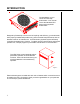
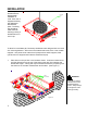
INTRODUCTION Congratulations on your choice of Poweramp docklevelers. Your manual covers the standard VEH Series series hydraulic docklevelers. Figure 1 Designed by Poweramp to be a marvel of simplicity and efficiency, your dockleveler, when properly installed will provide many years of trouble-free performance with an absolute minimum of maintenance. It's revolutionany hydraulic system efficiently controls and operates every function.
PREPARATION WARNING 1. Remove all debris from pit and sweep out. Barricade the work 2. Check entire dockleveler pit for proper construction according to approved/certified area to prevent unaupit drawings. Check to be sure that pit walls are square and plumb. Check electrithorized use of the unit cal service to the pit to assure it agrees with the correct location for the junction before installation has box. been completed.
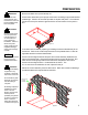
INSTALLATION Poweramp docklevelers are designed with installation in mind. Each unit is shipped with lifting lugs bolted thru the outboard joists. The lifting lugs should be used whenever lowering or lifting a dockleveler into or out of a pit. LIFTING LUG Figure 5 To allow for inconsistant pits, Poweramp docklevelers are designed with a nominal 3/4" shimming distance. Shims are to be located under each of the 3 rear vertical supports.
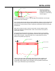
INSTALLATION 2. REAR PIT CURB ANGLE Remove the stacks of shims and weld to the dockleveler frame directly beneath the corresponding vertical support. DOCK FLOOR STRING LINE PIT FLOOR Figure 7 3. Position the dockleveler in the pit. The rear edge of the dockleveler must be tight against the rear pit curb angle. 4. Use 1/4" thick shims to shim the front of the dockleveler. Shims are to be placed under the 2 lip keeper/cross traffic supports and under the maintenance prop pivot point.
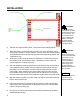
INSTALLATION REAR PIT CURB ANGLE TOP REAR FRAME ANGLE X X X X 3/8" SKIP WELD (6" WELD, 12" SKIP) X X WARNING REAR HINGE TUBE X X X X X X Figure 9 8. With the rear angle welded in place, cut and remove the shipping bands. 9. Raise the platform by external means (crane or fork truck) and place maintenance prop in position to support platform. Be sure shims are located between prop attachment point to the frame and pit floor before supporting platform with maintenance prop. 10.
INSTALLATION WARNING Always barricade the work area to prevent unauthorized use of the unit before maintenance is complete. Always lock off all electrical disconnects after raising platform and setting maintenance prop when service under the unit is required. More than one electrical disconnect switch may be required to de-energize the equipment. 15. Depress and hold the raise button until the maintenance prop can be positioned properly.
ADJUSTMENT AND TESTING While you were cycling the dockleveler upon completion of the installation, you should have noticed that the dockleveler would raise to a certain point after which time the lip would extend. Releasing the raise button would allow the dockleveler to lower to the full below dock position after which the lip would fold. Pressing the raise button would then cause the dockleveler to raise.
ADJUSTMENT AND TESTING If the dockleveler lip did not extend, or extended too early, the cable weight may need adjusting. The cable weight is located underneath the dockleveler directly behind the valve block. As the platform raises, the cable moves the valve lever. When the cable force exceeds the force necessary to shift the valve spool, the spool shifts causing the oil to flow to the lip cylinder.
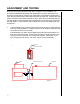
ADJUSTMENT AND TESTING Your dock leveler may be equipped with Auto Return to Dock. Auto Return to Dock is an operation available on VEH Series dock levelers that will automatically reposition the dock leveler into the stored, cross traffic position after the truck departs. This option utilizes a switch under the dock leveler and a target fastened to the lip. See Figure 13.
ADJUSTMENT AND TESTING Dock Leveler at cross traffic position. Lip fully folded, inside keepers. (Lip also fully folded when leveler on maintenance prop.) LIP KEEPER 1. Target not in sensing area of switch. 2. Switch "OFF" = open (no signal sent to load). 3. Switch indicator light "OFF". 4. The dock leveler does not automatically raise & return to dock. Figure 15 Dock leveler at full below dock position. Lip partially extended, outside keepers. 1. Target in sensin area of switch. 2.
OPERATION The VEH Series dockleveler is designed to compensate for +/- 12" of height difference between the loading dock and the truck bed. To position the dockleveler, the operator utilizes the VEH Series pushbutton controls. When the raise pushbutton is pushed and held, a motor is activated that in turn drives a hydraulic pump which raises the dockleveler platform. Releasing the pushbutton allows the platform to lower.
OPERATING INSTRUCTIONS WARNING Do not operate the unit if any personnel are on or in front of the unit. Do not operate the unit until the truck/ trailer is parked squarely against the dock bumpers. 1. Check to make sure truck is positioned squarely against dock bumpers. 2. Instruct the driver to remain at the dock until the loading/unloading process is complete. 3. Chock trailer wheels. 4. If loading dock is equipped with trailer restraint, engage restraint. 5.
PREVENTIVE MAINTENANCE Maintenance on your VEH Series Hydraulic dockleveler can be classified as both weekly and monthly. WEEKLY MAINTENANCE 1. At least once each week, operate the unit through all of its operating cycles to maintain lubrication. 2. Inspect the dockleveler platform hinge area and lip area. The hinge areas should be kept free of debris and dirt. Build up of foreign material in the hinge areas will cause abnormal operation.
PREVENTIVE MAINTENANCE 2. Check the hydraulic fluid level in the reservoir of the powerpack (i.e. motor/ pump/reservoir) when the dockleveler is safely supported by the maintenance prop. The fluid level should be approximately 2" from the top of the reservoir. A low fluid level or the use of non-recommended fluids will cause abnormal operation of the unit. BREATHER CAP RESERVOIR FLUID LEVEL 2" Figure 19 3.
PREVENTIVE MAINTENANCE SERVICING UNDER THE DOCKLEVELER If the maintenance to be performed requires access to the unit from the pit, support the dockleveler platform and lip with the maintenance prop. Position the prop behind the front header plate of the platform as illustrated in figure 15. Stay clear of the lip. The lip will fold after the platform has rested on the maintenance prop.
TROUBLESHOOTING GUIDE WARNING Always barricade the work area to prevent unauthorized use of the unit during repair or maintenance procedures. Always lock OFF all electrical disconnects when servicing the unit. Always stand clear of the dockleveler lip when working in front of the unit. Perform the following proceedures prior to beginning detailed troubleshooting: A. Check all fuses inside the control assembly(s). Replace any bad fuse with one of equivalent specification. B.
TROUBLESHOOTING GUIDE DOCK LEVELER (Continued) PROBLEM CONTINUED Leveler platform does not raise to its full height OR platform raises to full height but lip does not fully extend OR motor overcurrent device and/or overload device continuously tripping. CAUSE(S) SOLUTION(S) 2. Pressure relief valve set too low. 2. Locate valve. See Figure 10, page 8. Remove cover nut. Using Allen wrench, turn Allen screw CW approximately 1/2 turn. Check speed. If leveler continues to operate slowly, repeat above.
37 39 33 36 14 32 11 38 35 34 38 40 43 31 5" CHANNELS ON PLATFORM 18 16 15 17 16 19 *42 NOTE: POWERPACK IS REMOVED FROM THIS VIEW 29 41 1 28 27 2 9 26 8 5 13 30 10 25 29 20 6 21 22 3 7 23 24 CROSS SECTION OF DOCKLEVELER RETURN PRESSURE 4 44 45 46 POWERPACK DETAIL
PARTS LIST ITEM 1 2 3 4 5 6 7 8 9 10 11 12 13 14 15 *16 17 18 19 20 21 22 23 24 25 26 27 28 29 30 31 32 33 34 35 36 37 38 39 40 41 *42 43 44 45 46 QTY.
LIP CYLINDER 1 ITEM QTY. 1 2 3 4 5 6 7 1 1 1 1 1 1 2 3 5 4 6 PART NUMBER DESCRIPTION 0521-0109 0521-0110 0522-0087 0521-0003 0521-0004 0521-0002 0525-0059 WEAR RING PISTON SEAL CYLINDER HEAD "O" RING RETAINING RING SEAL - ROD SEAL KIT - INCLUDES ALL ABOVE HOIST CYLINDER 2 8 9 7 ITEM 1 2 3 4 5 6 7 8 9 10 QTY.