POWERSTOP-M TRUCK RESTRAINT INSTALLATION AND OPERATION MANUAL Job Name Job Number Serial Numbers Systems, Inc. P.O.
Table of Contents Safety ................................................................................................................... 1 Safety Alert Symbols ...................................................................................... 1 General Safety Precautions ............................................................................ 1 Introduction ........................................................................................................ 2-3 Installation ..................
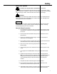
Safety Safety Alert Symbols This Safety Alert Symbol Means ATTENTION is Involved! The Safety Alert Symbol identifies important safety messages on equipment, safety signs, in manuals, or elsewhere. When you see this symbol, be alert to the possibility of personal injury or death. Follow the instructions in the safety message.
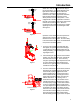
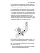
Introduction Poweramp. Read the entire manual before installing and/or operating the truck restraint. Poweramp mechanical truck restraints were designed to be compatible with almost all dock designs. See Figures 1 and 2. Figure 1 Pit Style Leveler Figure 2 Edge of Dock Poweramp mechanical restraints can be accompanied by a Dockalert light communication package and sign kit.
Introduction Red Light When not in use, the restraint must be kept in the stored position. If equipped with lights, the light selector switch should be in either the automatic or stored position depending on restraint model. Units equipped with automatic light operation should have the light control switch placed in the automatic postion. Units equipped with manual light operation must have the light control switch placed in the position that matches the restraint position.
Installation These installation instructions were written to guide you during the installation process. Please read and familiarize yourself with all sections of this manual prior to starting the installation. If you have any questions about the installation or operation of the Poweramp mechanical truck restraint, please consult the factory at (414) 2551510 before proceeding. Open and inspect all material upon delivery. Check contents against packing slip.
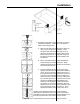
Installation Plumb Line 1" Main Achors Figure 7 4. Preparation of the anchor hole is necessary to assure a long lasting installation. Prepare the 1-1/8" diameter holes in the following manner: A. Blow the hole clean with compressed air, brush out using 1" nylon brush, blow clean again. Holes should be clean and sound. They may be dry or damp, but should be free of standing water or frost. Be sure rod fits into hole.
Installation Using the proper diameter bit, drill a hole into the base material to a depth of at least 1/2" or one anchor diameter deeper than the embedment required. The tolerances of the drill bit used should meet ANSI Standard B94.12. Blow the hole clean of dust and other material. Remove the inspection tag from the anchor and position the fixture. Do not expand the anchor prior to installation.
Installation If your mechanical restraint is equipped with a Dock alert light communication package, please continue to follow the installation instructions. If your unit is not equipped with lights, please turn to the operation section, page 9. INSTALLATION OF ELECTRICAL COMPONENTS When equipped with a light communication package, the mechanical restraint includes a prewired control box, outside light box, and (2) outside truck driver signs. Components such as conduit, fittings, anchors, etc.
Operation The Poweramp mechanical truck restraint was designed to work in conjunction with other dock equipment allowing the dock attendant to create a safer working environment. Before operating the equipment, be sure the rear of the trailer has been parked tight against the face of both dock bumpers. If your loading dock is equipped with a dock leveler, the hinged lip must be in the pendant, stored position prior to operating the restraint.
Operation OPERATION WITH MANUAL LIGHTS 1. Switch the inside control box light control switch to the released position. Verify that the green light has illuminated. 2. Verify that the trailer is parked tight against both bumpers. 3. Insert one end of the operating bar under the release lever on the left hand side of the restraint. 4. Lift up on the operating bar, causing the release lever to rotate, thus activating the restraint. With the restraint activated, the restraint arm will move vertically. 5.
Maintenance/Troubleshooting MAINTENANCE 1. Good housekeeping practice is the most commonly needed truck restraint requirement. Shipping and receiving docks are notorious for having wood scraps, steel banding and other debris laying at the front of the dock. Daily patrol truck restraint area and clean up dock. 2. Depending on the type of application, the truck restraints usually require lubrication every three months. Lubricate back track with an anti-seize lubricant. Lubricate linkage with 30 wt. oil. 3.
Maintenance/Troubleshooting 3. If signal lights, either inside or outside, fail to operate or operate incorrectly: NOTE: Both sets of lights are controlled from the same control box switch. A. Check bulbs. Replace as required. B. Check on/off switch. Repair or replace if needed. C. Check electrical power source. 4. If restraint is equipped with automatic light control and lights do not change properly, test relay in control box and proximity switch on restraint for proper operation.
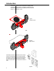
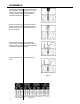
12 30 25 3 14 14 15 9 5 7 ITEM #14 IS COMMON TO ALL PIVOT POINTS 9 18 11 10 15 9 2 17 14 17 19 5 6 28 16 16 6 13 29 14 8 21 22 1 23 xx WA RN IN G xx xx xx xx xx xx xx xx xx xx xxxx xx xx xxxx xx xx xx xx xx xx xx xx xx xx xx xx xx x xx xx xx xxxx xx xx xx xx xx xx xx xxxx x xx xx xx xx xxxx xx xx xx xx xx xx xx xx xx xx xx xx xx xx xx xx xx xx xx xx xx xx xx xx xx xx xx xx xx xx xx xx xx xx xx xx xx xx xx x xx xx xx x xx x 26 4 20 31 21 OPTIONAL 24 32 Figure 12 12 14
BILL OF MATERIALS ITEM 1 *2 3 4 5 6 7 8 9 10 11 12 13 14 15 *16 17 18 19 20 21 22 23 *24 25 26 27 *28 29 30 *31 *32 QTY 1 1 1 1 4 4 1 2 3 2 2 1 1 21 5 2 2 10 1 2 2 6-8 1 2 2-3 1 1 2 1 2 2 1 PART NUMBER DESCRIPTION 9414-0034 0961-0148 9413-0049 9411-0023 9412-0148 9412-0149 9412-0180 0192-0053 9202-0042 9413-0044 0941-0011 0522-0002 9412-0160 9461-0006 2101-0165 2101-0182 9202-0043 2101-0189 2101-0039 2101-0057 0192-0052 2101-0180 2103-0001 0192-0056 2101-0085 5455-0005 2101-0181 2101-0156 2101-0018 941
Figure 13 14
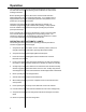
BILL OF MATERIALS ITEM QTY. PART NUMBER DESCRIPTION 1 2 3 4 5 6 7 8 9 10 11 12 1 2 2 1 1 2 2 2 1 1 1 1 7154-0002 7153-0006 3051-0046 7151-0002 7151-0003 7151-0026 7151-0011 7151-0006 7152-0006 1751-0034 1751-0033 2751-0125 SIGNAL LIGHT HOUSING ASSY.
SYSTEMS, INC. WARRANTY Powerstop Vehicle Restraint Systems, Inc. guarantees the materials, components, and workmanship in your Poweramp POWERSTOP to be of the highest quality and to be free of defects in material and workmanship for a period of one (1) year from date of shipment. Systems, Inc. further guarantees the hydraulic components on all Poweramp POWERSTOP for a period of one (1) year from date of shipment. The electrical components carry a one (1) year warranty (lights not included).