POWERSTOP-A TRUCK RESTRAINT INSTALLATION AND OPERATION MANUAL Job Name Job Number Serial Numbers SYSTEMS, INC. P.O.
(This Page Intentionally Left Blank)
Table of Contents Safety ................................................................................................................... 1 Safety Alert Symbols ...................................................................................... 1 General Safety Precautions ............................................................................ 1 Introduction ........................................................................................................ 2-4 Installation ..................
Safety Safety Alert Symbols This Safety Alert Symbol Means ATTENTION is Involved! The Safety Alert Symbol identifies important safety messages on equipment, safety signs, in manuals, or elsewhere. When you see this symbol, be alert to the possibility of personal injury or death. Follow the instructions in the safety message. WARNING Read these safety precautions before installing, operating or servicing the truck restraint. Failure to follow the safety practices could result in serious injury or death.
Introduction The Automatic Truck Restraint is a hydraulically activated vehicle restraint that is upwardly biased when activated. Two hooking ranges allow engagement with ICC bars that are positioned 7" to 11" from the bumper face and 12-1/2" to 30" off the drive approach. By rigidly mounting the restraint to a concrete pad or drive approach, restraining forces in excess of 22,800 pounds can be achieved.
Introduction WARNING This manual covers the Automatic Truck Restraint manufactured by Systems, Inc.. Read the entire manual before installing and/or operating the truck restraint. Automatic Truck Restraints were designed to be compatible with almost all dock designs. See Figures 1 and 2. Barricade the work area to prevent unauthorized use of the unit before installation has been completed.
Introduction Red Light CAUTION Green Light When not in use, the restraint must be kept in the stored position. If equipped with lights, the light selector switch should be in the automatic position. When the restraint is stored, the outside signal light is Green and the inside light is Red. See Figure 4. Restraint Stored Always store restraint when not in use to prevent damage.
Installation WARNING Barricade the work area to prevent unauthorized use of the unit before installation has been completed. These installation instructions were written to guide you during the installation process. Please read and familiarize yourself with all sections of this manual prior to starting the installation. If you have questions about the installation or operation of the Automatic Truck Restraint, please consult the factory at (414) 255-1510 before proceeding.
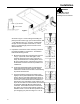
Installation WARNING Proper safety apparal should be worn when installing the truck restraint. Plumb line 1" Main Anchors Figure 7 as shown in Figure 7. After locating and marking the primary anchor locations (qty. 2) on the drive surface, drill 1-1/8" diameter holes 7 to 7-1/2" deep. If drill breaks through concrete at a depth of less than 6", consult factory. The remaining (6) 3/4" anchor holes can be drilled at this time. 4.
Installation Install remaining six anchors using the following procedure: Using the proper diameter bit, drill a hole into the drive approach to a depth of at least 1/2" or one anchor diameter deeper than the embedment required. The tolerances of the drill bit used should meet ANSI Standard B94.12. Blow the hole clean of dust and other material. Remove the inspection tag from the anchor and position the fixture. Do not expand the anchor prior to installation.
Installation INSTALLATION OF ELECTRICAL COMPONENTS When equipped with a Dock Alert II light communication package, the Automatic Truck Restraint includes a prewired control box, outside light box, and (2) outside truck driver signs and a hydraulic power unit. Components such as conduit, fittings, anchors, etc. are supplied by others. Quality workmanship using materials approved by code is required. CAUTION Have all electrical work performed only by qualified electricians.
Installation Figure 13 illustrates a mounting location on the inside building wall. In this location, damage from fork trucks must be considered. The routing of hydraulic and electrical lines from the powerpack to the restraint must be determined. Figure 13 Figure 14 illustrates a mounting location under a dockleveler. In this location, damage from the moving dockleveler parts must be considered. The routing of hydraulic and electrical lines from the powerpack to the restraint must be determined.
Installation 17” 10” 8” Conduit, flexible or rigid, must be connected between the limit switch on the restraint and the powerpack. Wiring to and from the restraint must be limited to restraint wires only. Do not run high voltage lines through the same conduit as restraint wires. Conduit and associated hardware to complete wiring and mounting of powerpack are to be supplied by others. If the powerpack will be mounted next to the truck restraint.
Operation WARNING Do not operate the unit if any personnel are on or in front of the unit. Do not operate the unit until the truck/trailer is parked squarely against the dock bumpers. The Poweramp Automatic Truck Restraint was designed to work in conjunction with other dock equipment allowing the dock attendant to create a safer working environment. Before operating the equipment, be sure the rear of the trailer has been parked tight against the face of both dock bumpers.
Operation 4. Activate the dock leveler and proceed to load/unload. 5. When loading/unloading of the truck is complete, return the dock leveler to the stored position. 6. Depress the "Store" pushbutton on the control panel and verify that the unit has stored.
Maintenance MAINTENANCE WARNING Always barricade the work area to prevent unauthorized use of the unit before maintenance is complete. 1. Good housekeeping practice is the most commonly needed truck restraint requirement. Shipping and receiving docks are notorious for having wood scraps, steel banding and other debris laying at the front of the dock. Daily patrol truck restraint area and clean up dock. 2.
Troubleshooting WARNING Always barricade the work area to prevent unauthorized use of the unit during repair or maintenance procedures. Always lock OFF all electrical disconnects when servicing the unit. Always stand clear of the dockleveler lip when working in front of the unit. Never work in the operating range of the restraint with power ON. Always check and either repair or replace burned out lights. Failure to do so could jeopardize dock attendant's safety.
Troubleshooting Hydraulic Troubleshooting Problem Restraint will not raise. Possible Solution(s) 1. Remove excess load from restraint. Unit is designed to raise no more than its own weight as a safety feature. 2. Strainer element plugged. Remove reservoir and clean or replace strainer element. Restraint moves very slowly. 1. Low hydraulic fluid. Add hydraulic fluid as needed. 2. Pump by-pass set too low. Pump by-pass adjustment is internal to pump, consult factory.
Electrical Troubleshooting PROBLEM Restraint does not raise or lower - Motor does not run, inside & outside lights do not work. POSSIBLE SOLUTION(S) 1. No voltage at control assembly. Check voltage input. 2. Blown fuse inside control assembly. Use voltmeter to test. WARNING: LINE SIDE OF FUSE IS ALWAYS HOT. LOCK OFF POWER TO CONTROL ASSEMBLY BEFORE REMOVING FUSE. 3. Defective contact block at power selector switch. Use voltmeter to test.
Electrical Troubleshooting - Continued PROBLEM Restraint does not lower - motor runs in pressure relief, inside & outside lights work. POSSIBLE SOLUTION(S) 1. Solenoid spool mechanically stuck ON. Remove spool from hydraulic block. Inspect block for contaminants. Test. Replace if necessary. NOTES: DO NOT RUN MOTOR WHEN SPOOL IS REMOVED FROM BLOCK. DO NOT OVERTIGHTEN COIL ON SPOOL. N UT IS TO ONLY BE TIGHTENED TO PREVENT COIL FROM FALLING OFF SPOOL. DO NOT OVERTIGHTEN SPOOL INTO BLOCK.
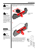
36 3 14 9 5 ITEM #14 IS COMMON TO ALL PIVOT POINTS 14 11 10 15 9 39 9 15 17 30 17 14 15 7 6 13 31 39 35 9 34 14 26 19 TO “B” RELEASE CYLINDER 8 21 12 22 TO “A” RELEASE CYLINDER TO “B” 33 TO “A” 32 12 16 25 18 SPRING IS SHOWN REMOVED FROM ITEM #26 FOR CLARITY 40 2 28 24 4 1 20 OPTIONAL 38 37 29 Figure 18 18 21 23
BILL OF MATERIALS ITEM QTY PART NUMBER DESCRIPTION 1 2 3 4 5 6 7 8 9 10 11 12 13 14 15 16 17 18 19 20 21 22 23 24 25 26 27 28 * 29 30 31 32 33 34 35 36 * 37 * 38 39 40 1 1 1 1 3 4 1 2 4 2 2 2 2 23 5 1 2 1 3 2 2 6 1 2 1 1 1 2 1 1 1 1 2 1 1 2 2 2 12 1 9414-0035 0961-0148 9413-0049 9411-0023 9412-0148 9412-0149 9412-0187 0192-0053 9202-0042 9413-0044 0941-0011 9904-0097 9412-0185 9461-0006 2101-0165 2101-0098 9202-0043 2101-0163 2101-0039 2101-0057 0192-0052 2101-0180 2103-0001 2101-0182 2101-0018 0524-
8 2 3 4 6 7 5 12 PO WE RA MP ST OR ED AC TI VAT ED AU TO MA TIC BY PA SS OFF AC TI VA TE D ON POW ER Figure 18 20
BILL OF MATERIALS ITEM QTY. PART NUMBER DESCRIPTION 1 2 3 4 5 6 7 8 9 10 11 12 1 2 2 1 1 2 2 2 1 1 1 1 7154-0002 7153-0006 3051-0046 7151-0002 7151-0003 7151-0026 7151-0011 7151-0006 7152-0006 1751-0034 1751-0033 9-K0-000-0-B SIGNAL LIGHT HOUSING ASSY.
RELEASE CYL (BLIND END) RELEASE CYL (ROD END) 10 14 5 13 2 9 4 1 3 6 12 11 3 CAPACITOR WIRING DETAIL NOTE: BASE WELDMENT (ITEM #1) & JUNCTION BOX (ITEM #6) SHOWN REMOVED FOR CLARITY.
BILL OF MATERIALS ITEM QTY.
SYSTEMS, INC. WARRANTY Powerstop Vehicle Restraint Systems, Inc. guarantees the materials, components, and workmanship in your Poweramp POWERSTOP to be of the highest quality and to be free of defects in material and workmanship for a period of one (1) year from date of shipment. Systems, Inc. further guarantees the hydraulic components on all Poweramp POWERSTOP for a period of one (1) year from date of shipment. The electrical components carry a one (1) year warranty (lights not included).