PowerHook Truck Restraint Owner’s Manual 2003 Addendum POWERAMP • Division of Systems, Inc. • W194 N11481 McCormick Drive • Germantown, WI 53022 800.643.5424 • fax: 262.255.4199 • www.docsystemsinc.com • techservices@docksystemsinc.com Printed in U.S.A. Copyright © 2003 Manual No. 4111-0010 July 2003 Rev.
Table of Contents Page Safety Recognize Safety Information . . . . . . . . . . . . . . . . . . . . . . . . . . . . . . . General Operational Safety Precautions . . . . . . . . . . . . . . . . . . . . . . Operational Safety Precautions . . . . . . . . . . . . . . . . . . . . . . . . . . . . . Maintenance Safety Precautions . . . . . . . . . . . . . . . . . . . . . . . . . . . . Safety Decals . . . . . . . . . . . . . . . . . . . . . . . . . . . . . . . . . . . . . . . . . . . .
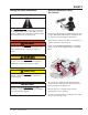
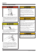
SAFETY Recognize Safety Information General Operational Safety Precautions Safety-Alert Symbol The Safety-Alert Symbol identifies important safety messages on equipment, safety signs, in manuals, or elsewhere. When you see this symbol, be alert to the possibility of personal injury or death. Follow the instructions in the safety message. Read and understand the operating instructions and become thoroughly familiar with the equipment and its controls before operating the dock leveler.
SAFETY Operational Safety Precautions Learn the safe way to operate this equipment. Read and understand the manufacturer's instructions. If you have any questions, ask your supervisor. Stay clear of dock leveling device when freight carrier is entering or leaving area. Chock/restrain all freight carriers. Never remove the wheel chocks until loading or unloading is finished and truck driver has been given permission to drive away.
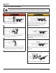
SAFETY Do not use dock leveling device if freight carrier is too high or too low. Do not overload the dock leveling device. Do not operate any equipment while under the influence of alcohol or drugs. Do not leave equipment or material unattended on dock leveling device.
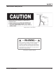
SAFETY Maintenance Safety Precautions ALWAYS disconnect electrical power source and ground wire before welding on dock leveler. DO NOT ground welding equipment to any hydraulic or electrical components of the dock leveler. Always ground to the dock leveler frame. Failure to follow these instructions may result in damage to dock leveler and/or serious personal injury or death. Hydraulic and electrical power must be OFF when servicing the equipment.
SAFETY Dock Leveler Safety Decals Safety Decal on Leveler Frame Safety Decal on Platform Cylinder 4111-0010 — December 2004 5
INTRODUCTION This page intentionally left blank 6 4111-0010 — December 2004
INTRODUCTION General Information Congratulations on your choice of a Poweramp PowerHook truck restraint. This manual addendum covers the PowerHook Truck restraint operating system updates since March 1, 2003. Designed by Poweramp to be a marvel of simplicity and efficiency, your truck restraint, when properly installed, will provide many years of trouble-free performance with an absolute minimum of maintenance. Its revolutionary hydraulic system efficiently controls and operates every function.
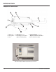
INTRODUCTION Component Identification A B C J F H E D G A — Regeneration Valve B — Hook Cylinder C — Hook D — Guide Track-Slide Rod E — Guide Track F — Sensor, Magnetic Reed Switch (Replaces Proximity Switch) G — Positioning Cylinder H — Guide Track Harness - Includes 4 Magnetic Reed Switches, Assembled J — Hook Lowered Sensor Target New Telemechanique “TWIDO” Programmable Logic Controller 8 4111-0010 — December 2004
INSTALLATION The following Installation Instructions are from our previous Installation Manual.
INSTALLATION 10 4111-0010 — December 2004
INSTALLATION 4111-0010 — December 2004 11
INSTALLATION 12 4111-0010 — December 2004
INSTALLATION 4111-0010 — December 2004 13
INSTALLATION NOTE: See Adjustments Section for new style hook sensor adjustments. This is the old style proximity switch. Do not use.
INSTALLATION 4111-0010 — December 2004 15
INSTALLATION 16 4111-0010 — December 2004
INSTALLATION 4111-0010 — December 2004 17
INSTALLATION 18 4111-0010 — December 2004
INSTALLATION 4111-0010 — December 2004 19
INSTALLATION 20 4111-0010 — December 2004
INSTALLATION 4111-0010 — December 2004 21
OPERATION Operating Instructions Stay clear of dock leveler when freight carrier is entering or leaving dock area. DO NOT move or use the dock leveler if anyone is under or in front of leveler. Keep hands and feet clear of pinch points. Avoid putting any part of your body near moving parts. Failure to follow these instructions may result in severe personal injury or death. DO NOT overload the dock leveler. DO NOT operate any equipment while under the influence of alcohol or drugs.
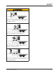
OPERATION SEQUENCE OF OPERATION NORMAL SEQUENCE OF OPERATION BYPASS 1. Check that the truck/trailer is positioned squarely against the dock bumpers. - Inside Red Light -Outside Green Light 1. Check that the truck/trailer is positioned squarely against the dock bumpers. 2. Push ENGAGE button to activate restraint. - Inside Green Light -Outside Red Light 3. Visually inspect restraint for proper engagement.
OPERATION PowerHook Light Sequence CONDITION LIGHTS INSIDE OUTSIDE STORED BEGIN/END (O/4) RED (O/4) GREEN IN MOTION (O/8) AMBER (O/5) (O/8) RED & STROBE HOOKED (O/7) GREEN (O/5) RED TRUCK PULLS (O/7) (O/8) GREEN/AMBER (O/5) (O/8) RED/STROBE OVERRIDE (O/7) (O/8) GREEN/AMBER (O/5) (O/8) RED/STROBE MISSED ICC (O/8) 30sec (O/4) AMBER (TIME) RED (O/5) 30sec (O/4) RED (TIME) GREEN STROBE (O/8) (O/6) (O/8) BLUE/AMBER (O/5) (O/8) RED/STROBE (O/8) AMBER (O/5) (O/8) RED/STROBE TIMEOUT (FAILU
MAINTENANCE Service Dock Leveler/Restraint Safely F E D C A— Tagout Device B — Lockout Device C — Lockout Device When service under the dock leveler is required, always lock all electrical disconnects in the OFF position after raising the platform and engaging the maintenance prop. Failure to do this may result in serious personal injury or death. Always stand clear of the dock leveler lip when working in front of the dock leveler.
MAINTENANCE Periodic Maintenance C B A On select models an inspection plate is provided in the platform floor for ease of maintenance and pit inspection. Others must be serviced from under the leveler.
MAINTENANCE P Daily Maintenance • Make sure that all the Inside and Outside signal lights work. N Q Weekly Maintenance • Operate the dock leveler and PowerHook through the complete operating cycle to maintain lubrication. NOTE: To thoroughly inspect the platform hinge area, put the platform in the full below-dock position. M • Inspect the platform hinge and the lip hinge areas. The hinge areas must be kept free of dirt and debris.
ADJUSTMENT AND TESTING Testing PowerHook Operating Range NOTE: Test operating range of PowerHook without truck/trailer backed into dock. When service under the dock leveler is required, always lock all electrical disconnects in the OFF position after raising the platform and engaging the maintenance prop. Failure to do this may result in serious personal injury or death.
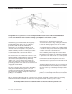
ADJUSTMENTS Adjust PowerHook Operating Range 4. Adjust the upper vertical limit of PowerHook operating range if necessary. A. Locate the hook cylinder assembly and the hold down cylinder assembly. See Figure 25. The length of the threaded eye on the hold down cylinder will determine the upper vertical limit of the hook movement. B. Disconnect the Hydraulic hose from the hold down cylinder. Cap off the open fittings to prevent fluid loss and to prevent contamination from entering the system. F.
ADJUSTMENTS Adjust PowerHook Operating Range 5. Adjust the lower vertical limit of hook operating range if necessary. A. A B C D E Locate the proximity switch that is mounted in the bracket located on the trunnion for the hook cylinder. Locate the target for the switch. See Figure 27. NOTE: The position of the target in relation to the switch will determine the lower travel limit of the hook. When the hook lowers, the target is positioned into the sensing area of the proximity switch.
ADJUSTMENTS Adjust PowerHook Operating Range Start adjustments at 10o’clock position Figure 28 4111-0010 — December 2004 31
OPTIONAL EQUIPMENT ADJUSTMENTS Adjust Dock Leveler and Truck Restraint Interlock Dock Leveler and Truck restraint Interlock When service under the dock leveler is required, always lock all electrical disconnects in the OFF position after raising the platform and engaging the maintenance prop. Failure to do this may result in serious personal injury or death.
OPTIONAL EQUIPMENT ADJUSTMENTS Adjust & Test Dock Leveler and Truck Restraint Interlock 1. The dock leveler should be in the cross traffic position before beginning tests. 2. Back a truck/trailer with RIG bar into dock. A test fixture may be used to simulate the RIG bar. Use care to avoid damage to the equipment or harm to the operator. 3. Press the RAISE push button. The dock leveler should NOT raise. If the leveler did not raise, proceed with step 4.
OPTIONAL EQUIPMENT ADJUSTMENTS Adjust Auto Return To Dock (ARTD) Adjust the ARTD as Follows: D E F C When service under the dock leveler is required, always lock all electrical disconnects in the OFF position after raising the platform and engaging the maintenance prop. Failure to do this may result in serious personal injury or death.
OPTIONAL EQUIPMENT ADJUSTMENTS IMPORTANT 6. Turn ON electrical power to the dock leveler. Anytime proximity switch and target are adjusted, always check for interference between target and switch before operating the leveler. Damage to switch will occur if the target contacts the switch. 7. Disengage the maintenance prop. The maximum torque for proximity switch lock nuts is 27 N•m (29 lb-ft). Damage to switch will occur if maximum torque is exceeded. 9.
OPTIONAL EQUIPMENT ADJUSTMENTS Full Below-Dock Position Lip Fully Extended Position Lip Keeper Whenever the platform lip is at the fully extended position, the following conditions will exist for a normally operating ARTD: • Target not in the sensing area of proximity switch. Whenever the platform lip is at the full below-dock position, the following conditions will exist for a normally operating ARTD: • Proximity switch OFF (open) (no signal sent to the control panel).
TROUBLESHOOTING POWERHOOK When service under the dock leveler is required, always lock all electrical disconnects in the OFF position after raising the platform and engaging the maintenance prop. Failure to do this may result in serious personal injury or death. Always post safety warnings and barricade the work area at dock level and ground level to prevent unauthorized use of the dock leveler before maintenance is complete. Failure to do this may result in serious personal injury or death.
TROUBLESHOOTING POWERHOOK Symptom Possible Cause Three-phase units only: 3 Phase units only - no Restraint does not voltage is present on one operate. Motor energizes line. but does not run. NOTE: A motor that is If motor hums, but does missing voltage on one line not run, overload device is said to be single-phased. should trip. Solution Check for blown fuses at branch circuit disconnect. Replace fuse. Determine cause of blown fuse. Check motor starter as follows: 1.
TROUBLESHOOTING POWERHOOK Symptom Possible Cause Solution Restraint does not fully extend or motor overcurrent device and/or overload device continuously tripping. Low hydraulic fluid. Add fluid, see Maintenance section for proper fluid level and type. Restraint lowers, fully extends but does not raise. Pump operates in pressure relief. Solenoid “D” valve stuck ON. Locate solenoid (See Parts: Valve Block). Remove coil from cartridge valve and cartridge valve from valve block.
TROUBLESHOOTING POWERHOOK Symptom Restraint extends from stored position without fully lowering. Possible Cause Solution Proximity switch at trunnion that senses when restraint lowered target out of adjustment. Locate switch on hook trunnion. Observe indicator light at controller input (#3) that receives signal from switch. Input light should only turn ON when restraint fully lowered. If this does not occur, adjust target counterclockwise. See Adjustments section: Adjust PowerHook Operating Range.
TROUBLESHOOTING POWERHOOK Symptom Possible Cause Restraint does not lower Solenoid “D” valve stuck off. at all from stored position. Pump operates in pressure relief (restraint does not extend). Solution Locate solenoid (See Parts: Valve Block). Remove coil from cartridge valve and cartridge valve from valve block. -Check valve for contaminant's and/or damage. -Replace valve if damaged. -Carefully wipe valve with clean rag (do not damage “O” rings on valve). -Check valve block for contaminant's.
TROUBLESHOOTING POWERHOOK Symptom Restraint only partially lowers from stored position. Pump operates in pressure relief (Restraint does not extend). Restraint fully lowers from stored position but does not extend. Possible Cause Solution Obstruction preventing the restraint from lowering. Remove obstruction. Fluid flow to positioning cylinder blocked. Locate the needle valve that controls fluid flow to the cylinder.
TROUBLESHOOTING POWERHOOK Symptom Restraint engages truck/trailer RIG bar but does not automatically shut OFF. Pump operates in pressure relief. Possible Cause Pressure switch trip point set too high. Restraint extends from Solenoid “B” valve stuck RIG bar engaged ON, or solenoid(s) “C1” or position, fully lowers but “C2” stuck OFF. does not retract. Solution Pressure switch is factory set. Do not attempt to adjust in field. Return to factory for adjustment or replace switch with factory pre-set unit.
TROUBLESHOOTING POWERHOOK Symptom Possible Cause Solution Lowered restraint returns to fully retracted position but unit does not automatically shut OFF. Pump Operates in pressure relief. Restraint remains lowered. Proximity switch on rear of (closest to rear pit wall) guide track that senses when restraint fully retracted out of adjustment. Locate switch on rear of guide track. Observe indicator light at controller input (#6) that receives signal from switch.
TROUBLESHOOTING DOCK LEVELER Symptom Platform does not rise. Pump operates in pressure relief mode. Possible Cause Solution Heavy object(s) on platform. Remove object(s) from platform. NOTE: For safety reasons, the dock leveler is designed to lift only the platform’s own weight. Dock leveler binds. Check for visible obstructions that could cause binding. Remove obstructions. If no obstructions found, call Poweramp Technical Services. See inside back cover for phone number and address.
TROUBLESHOOTING DOCK LEVELER Symptom Possible Cause Solution Platform does not rise to Low hydraulic fluid. full height. Add fluid, see Maintenance section for proper fluid level and type. Platform DOES rise to full height, but lip DOES NOT extend or extend fully. Low hydraulic fluid. Add fluid, see Maintenance section for proper fluid level and type. Logic block (valve) lever cable weight too low on cable. Adjust cable weight.
PARTS A,B D Item Quantity Part Number A B C 1 1 1 D 1 0961-0083 0961-0085 * 9511-0004 9512-0429 Description Proximity Switch with Harness (INTERLOCK Feature Only) Proximity Switch with Harness (ARTD Feature Only) Push Button Controller J-Box, Standard (4 x 4 in. Metal Box) J-Box, Cold Weather (5 x 5 in. Plastic Box) * Provide dock leveler serial number, voltage, phase, and options when calling or faxing controller orders.
PARTS Powerhook Guidetrack Components C D E Item Quantity Part Number A B C D E F A-F 1 1 1 1 1 1 1 0521-0143 0521-0144 0521-0145 2101-0196 2101-0202 2101-0203 0524-0075 D F A D E B D E Description Guide Track - Aluminum Cable Assembly - Powerhook - Standard Sensor Mounting Bracket Nylon Lock Nut, 10-32 UNF Round Head Machine Screw, 10-32 UNF x 1/2, Stainless Steel Round Head Machine Screw, 10-32 UNF x 3/4, Stainless Steel Powerhook Guide Track Assembly Complete *Provide dock leveler and/or Po
PARTS Powerhook Components A B C D U V W X Q R S T L N H J G E F O P M Item Quantity Part Number A 1 1 1 1 1 1 1 1 1 1 1 1 1 1 1 1 1 1 1 1 1 1 1 1 8581-0090 8585-0064 7054-0010 9904-0068 2101-0012 2101-0058 0522-0061 2101-0057 2101-0058 2101-0059 0524-0075 0526-0005 0526-0006 2101-0004 2101-0052 2101-0042 0522-0062 2101-0041 2101-0051 2101-0055 2101-0058 2101-0059 2101-0068 7052-0005 B C E F G H J K L M M N O P Q R S T U V W X Description Regeneration Valve Valve Block Assembly - Regenerat
PARTS Power Pack Assembly J L K M H D G E C F AC AB N P Q B AA R Z S Y A W T X U T V 50 4111-0010 — December 2004
PARTS Power Pack Assembly Item Quantity Part Number A B C D E F 2 2 1 1 1 2 1 4 1 1 1 1 1 1 1 1 1 1 1 1 2 1 1 1 1 1 1 2 2 2 1 2101-0039 9301-0029 9302-0014 9301-0199 9301-0027 9302-0012 9301-____ 1 2101-0016 9301-0028 9303-0002 9302-0017 9904-0001 0521-0017 0521-0007 3411-____ 2 0521-0015 0521-0014 9301-0024 9302-0009 9303-0003 9301-0014 9301-0015 9301-0016 0521-0016 9301-0009 9301-0082 9301-0008 9301-0003 9301-0004 2101-0063 9395-____ 1 G H J K L M N P Q R S T U V W X Y Z AA AB AC 1 2 Description N
PARTS PowerHook Valve Body Assembly 1 2 3 4 6 5 7 8 9 20 10 19 21 18 11 15 17 Item # 1 14 13 12 16 Part Description Cartridge Valve - 4-Way - 2-Position Block Label Function A 2,5,8,12,14 Delta Coil 3 Elbow 90° Fitting 4 Cartridge Valve - 3-Way - 2-Position 6 Pressure Switch Assembly 7 Cartridge Valve - 3-Way - 2-Position 9 Elbow 45° Fitting 10 11 13 Cartridge Valve - 2-Way - N.C.
MISCELLANEOUS Customer Information A NOTE: Refer to illustration for left/right orientation of dock leveler. The model/serial number decal (A) is located on the right platform joist near the front (lip) of dock leveler. When you receive your PR dock leveler, write down the dock leveler model and serial number in the form provided. This will help ensure safe keeping of the numbers in the event the model/serial number decal (A) becomes lost or damaged. Also, write down Systems, Inc.
SYSTEMS, INC. WARRANTY PowerHook Truck Restraint All PowerHook vehicle restraints feature a full two (2) year base warranty on all structural, hydraulic and electrical parts, including freight and labor charges in accordance with Systems, Inc’s Standard Warranty Policy. Structural and hydraulic components carry an additional full three (3) year extended warranty with parts and labor. Systems, Inc.