POWERHOLD AND POWERHOLD SC TRUCK RESTRAINT INSTALLATION AND OPERATION MANUAL Job Number Job Name Serial Numbers SYSTEMS, INC. P.O.
INDEX SECTION I. INSTALLATION A. B. C. II. DESCRIPTION OF OPERATING MODES ................................................................................. DESCRIPTION OF SIGNAL LIGHTS ......................................................................................... SIGNAL LIGHTS AND ALARM SEQUENCE OF OPERATION ................................................... OPERATING NOTES ................................................................................................................
NOTE: Control unit shipped may be different than what is shown. NOTE: Outside Light Assembly shipped may be different than what is shown.
INSTALLATION MOUNTING AND ANCHORING Inspect installation location: The POWERHOLD restraint will require solid anchors to assure proper operation. Optimum installations will have both a concrete drive and a poured concrete dock face so that anchor bolts can be well secured. Twelve 1/2" anchor bolt mounting holes are re provided. However, 6 base or 6 wall may be used where cold induced frost heave will be a factor or mounting conditions do not allow use of all 12 mounting holes.
INSTALLATION CONTINUED ELECTRICAL Refer to the drawings indicated in Table I for the electrical installation. The drawings are attached to this manual. IMPORTANT Make sure that the power supply requirement(s) as shown on the electrical drawings and on the decal of the control assembly(s) are the correct requirement(s) for the application.
GENERAL INFORMATION DESCRIPTION OF OPERATING MODES A. "NORMAL" OPERATING MODE Used to operate the POWERHOLD restraint to engage the truck ICC bar. An auto-raise cycle will be activated by momentary pressure on the "LOCK" push button (Note: Pressure on the "LOCK" push button must be maintained until the inside lights change from red to amber). An AUTO-LOWER cycle will be activated by momentary pressure on the "UNLOCK" push button.
GENERAL INFORMATION CONTINUED DESCRIPTION OF SIGNAL LIGHTS: A. INSIDE SIGNAL LIGHTS. These lights are typically located on the PLC/ LOGIC control assembly. the assembly housing the light is to be mounted in a location that is clearly visible to the dock attendant. WHEN THE LIGHT IS ON: RED LIGHT R • IT INDICATES TO THE DOCK ATTENDANT THAT IT IS NOT OK TO ENTER THE TRUCK. THE TRUCK ICC BAR IS NOT ENGAGED BY THE POWERHOLD RESTRAINT. THE BYPASS MODE AND WHEEL CHOCKS MAY BE REQUIRED.
GENERAL INFORMATION CONTINUED SIGNAL LIGHTS AND ALARM SEQUENCE OF OPERATION A. "NORMAL" operating mode - truck ICC bar engaged. 1. The POWERHOLD restraint is in the fully lowered (stored) position. Limit switch "LS3" is closed. Outside light = Green Inside light = Red Alarm = Off 2. The POWERHOLD restraint is activated. a. The unit leaves the fully lowered (stored) position. Limit switch "LS3" is open. Outside light = Red Inside light = Amber Alarm = Off b.
GENERAL INFORMATION CONTINUED SIGNAL LIGHTS AND ALARM SEQUENCE OF OPERATION CONTINUED. D. The unit reaches the fully lowered (stored) position. Limit switch"LS3" is closed. Outside light = Green Inside light = Red Alarm = Off D. "BYPASS" operating mode Outside light = Red at all times Inside light = Amber at all times Alarm = Off at all times OPERATING NOTES A.
GENERAL INFORMATION CONTINUED Also, the restraint will automatically shut off after the 13 second delay if the unit reaches the stored position but the "LS3" limit switch in the unit has failed "OPEN". D. If power is lost after the restraint is activated, the automatic raise and lower cycles will be disabled. Thus, when power is restored the restraint must be reactivated to either the fully raised ICC bar engaged position or the stored position.
OPERATING INSTRUCTIONS NORMAL OPERATION 1. Set the "ON-OFF" switch to "ON". 2. Set the "NORMAL-BYPASS" key switch to "NORMAL". 3. Requirements for proper restraint operation are that the truck be parked perpendicular to the loading dock area with its ICC bar from 4-1/2" to 14-1/2" from the face of the dock when 4-1/2" bumpers are used. If 6" bumpers are used, the horizontal range would be from 6" to 16" from the face of the dock. 4.
MAINTENANCE CLEANING The POWERHOLD restraint should be kept free of debris, ice, dirt and sand. Build-ups of foreign material, especially on the top of the slide block assembly, could result in abnormal operation of the restraint. LUBRICATION Lubrication should be performed on a monthly basis. Use Lubriplate No. 18339 multipurpose grease or equivalent. Remove all of the old grease from the slide block guide channels and from the top of the slide block before applying the new grease.
MECHANICAL RELEASE The POWERHOLD restraint is equipped with a mechanical release that can be utilized in the event of an electric and/or hydraulic failure which prevents the unit from releasing the truck ICC bar via normal operating methods.
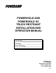
POWERHOLD END RELEASE 18 30 31 32 34 33 25 20 36 21 19 17 40 23 38 29 35 41 15 16 39 11 26 28 12 24 22 13 8 27 36 4 3 6 9 1 7 2 5 11
POWERHOLD END RELEASE PARTS LIST ITEM DESCRIPTION PART NUMBER 1 HOUSING WELDMENT 9414-0029 2 FRONT COVER PLATE 9411-0012 3 SCREW 2101-0099 4 LATCH WELDMENT ASSY For 23" Restraint Weldment *Complete Assembly with Prox Switches 9414-0037 4 LATCH WELDMENT For 19" Restraint Weldment *Complete Assembly with Prox Switches 9414-0042 5 PROX. SWITCH-RATCHET AC-RELAY EQUIPPED 0961-0035 5 PROX.
POWERHOLD END RELEASE CONTINUED ITEM DESCRIPTION PART NUMBER 22 BAR-WEATHERSEAL HOLD DOWN 9411-0007 23 BAR-REMOVABLE TRACK STOP (LH/RH) 9412-0063 24 ELECTRICAL BOX 2752-0029 25 SHROUD 9411-0015 26 COVER & GASKET (ELEC.
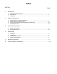
POWERHOLD SELF CONTAINED 46 45 49 48 55 47 42 43 44 45 43 51 53 54 14 52 50 1
POWERHOLD SC (SELF CONTAINED) POWERPACK PARTS ITEM DESCRIPTION PART NUMBER 42 SHROUD - MOTOR 9412-0107 43 CAPSCREW 2101-0009 44 90 DEGREE STREET ELBOW 9301-0034 45 HOSE ADAPTOR - 90 DEGREE ELBOW 0521-0076 46 HOSE ASSY - 14" 9904-0038 47 PUMP 9301-0084 48 FILTER 9301-0085 49 BREATHER CAP 9301-0020 50 RESERVOIR 9303-0010 51 NIPPLE 9301-0045 52 MOTOR 3411-0008 53 TEE 9301-0012 54 HOSE ASSY - 11" 9904-0041 55 ELEMENT 9301-0086 15
SYSTEM'S, INC. STANDARD WARRANTY POWERHOLD VEHICLE RESTRAINT Poweramp warrants the locking unit, welded main frame, hydraulic cylinders and hoses, and all electrical components to be free of defects in material and workmanship for a period of one (1) year when installed and used in accordance with the Powerhold Owner’s Manual. Systems, Inc. further guarantees the hydraulic components except for the solenoid valves on all Powerhold units for a period of one (1) year from date of shipment.