POWERHOLD SC TRUCK RESTRAINT INSTALLATION AND OPERATION MANUAL Job Number Job Name Serial Numbers SYSTEMS, INC. P.O.
.
INDEX SECTION I. INSTALLATION A. B. C. II. DESCRIPTION OF OPERATING MODES ................................................................................. DESCRIPTION OF SIGNAL LIGHTS ......................................................................................... SIGNAL LIGHTS AND ALARM SEQUENCE OF OPERATION ................................................... OPERATING NOTES ................................................................................................................
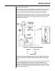
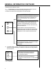
NOTE: Control unit shipped may be different than what is shown.
INSTALLATION MOUNTING AND ANCHORING Inspect installation location: The POWERHOLD restraint will require solid anchors to assure proper operation. Optimum installations will have both a concrete drive and a poured concrete dock face so that anchor bolts can be well secured. Twelve 1/2" anchor bolts are recommended, however, sixteen mounting holes are provided.
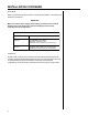
INSTALLATION CONTINUED ELECTRICAL Refer to the drawings indicated in Table I for the electrical installation. The drawings are attached to this manual. IMPORTANT Make sure that the power supply requirement(s) as shown on the electrical drawings and on the decal of the control assembly(s) are the correct requirement(s) for the application.
GENERAL INFORMATION DESCRIPTION OF OPERATING MODES A. "NORMAL" OPERATING MODE Used to operate the POWERHOLD restraint to engage the truck ICC bar. An auto-raise cycle will be activated by momentary pressure on the "LOCK" push button (Note: Pressure on the "LOCK" push button must be maintained until the inside lights change from red to amber). An AUTO-LOWER cycle will be activated by momentary pressure on the "UNLOCK" push button.
GENERAL INFORMATION CONTINUED DESCRIPTION OF SIGNAL LIGHTS: A. INSIDE SIGNAL LIGHTS. These lights are typically located on the PLC/ LOGIC control assembly. the assembly housing the light is to be mounted in a location that is clearly visible to the dock attendant. WHEN THE LIGHT IS ON: IT INDICATES TO THE DOCK ATTENDANT THAT IT IS NOT OK TO ENTER THE TRUCK. THE TRUCK ICC BAR IS NOT ENGAGED BY THE POWERHOLD RESTRAINT.
GENERAL INFORMATION CONTINUED SIGNAL LIGHTS AND ALARM SEQUENCE OF OPERATION A. "NORMAL" operating mode - truck ICC bar engaged. 1. The POWERHOLD restraint is in the fully lowered (stored) position. Limit switch "LS3" is closed. Outside light = Green Inside light = Red Alarm = Off 2. The POWERHOLD restraint is activated. a. The unit leaves the fully lowered (stored) position. Limit switch "LS3" is open. Outside light = Red Inside light = Amber Alarm = Off b.
GENERAL INFORMATION CONTINUED the fully lowered position). SIGNAL LIGHTS AND ALARM SEQUENCE OF OPERATION CONTINUED. c. The unit reaches the fully lowered (stored) position. Limit switch "LS3" is closed. Outside light = Green Inside light = Red Alarm = Off C. "BYPASS" operating mode Outside light = Red at all times Inside light = Amber at all times Alarm = Off at all times OPERATING NOTES A.
GENERAL INFORMATION CONTINUED return cycle (with alarm) will be activated). 2. Automatic return cycle (no ICC bar) and automatic lower cycle: If the restraint does not reach the stored position within approximately 13 seconds after leaving the fully raised ICC bar engaged position or the fully raised no ICC bar engaged position, the restraint will automatically shut off. Failure to reach the stored position can be due to an obstruction preventing the restraint from lowering.
OPERATING INSTRUCTIONS NORMAL OPERATION 1. Set the "ON-OFF" switch to "ON". 2. Set the "NORMAL-BYPASS" key switch to "NORMAL". 3. Requirements for proper restraint operation are that the truck be parked perpendicular to the loading dock area with its ICC bar from 4-1/2" to 14-1/2" from the face of the dock when 4-1/2" bumpers are used. If 6" bumpers are used, the horizontal range would be from 6" to 16" from the face of the dock. 4.
MAINTENANCE CLEANING The POWERHOLD restraint should be kept free of debris, ice, dirt and sand. Build-ups of foreign material, especially on the top of the slide block assembly (P/N 9413-0022), could result in abnormal operation of the restraint. LUBRICATION Lubrication should be performed on a monthly basis. Use Lubriplate No. 18339 multipurpose grease or equivalent.
MECHANICAL RELEASE SIGNAL LIGHTS CHECK To assure dock attendant safety, check to make sure that the inside and outside signal lights function correctly. This check should be performed on a weekly basis. The correct sequence of light operation can be found in the general information section of this manual.
POWERHOLD END RELEASE 18 30 31 32 34 33 25 20 36 21 19 17 40 23 38 29 35 41 15 16 39 11 26 28 12 24 22 13 8 27 36 4 3 6 9 1 7 2 5 11
POWERHOLD END RELEASE PARTS LIST ITEM DESCRIPTION PART NUMBER 1 HOUSING WELDMENT 9414-0029 2 FRONT COVER PLATE 9411-0012 3 SCREW 2101-0099 4 LATCH WELMENT 9413-0027 5 PROX. SWITCH-RATCHET 0961-0035 6 LIMIT SWITCH-STORED 0961-0037 7 PROX. SWITCH-CYLINDER 0961-0035 8 SPRING SERVALITE 0941-0009 9 CAP SCREW 2101-0100 10 PROX.
POWERHOLD END RELEASE CONTINUED ITEM DESCRIPTION PART NUMBER 27 SCREW - FRONT PLATE 2101-0076 28 WEATHERSEAL 0192-0016 29 HOSE ASSY - 22" 9904-0039 30 HYDRAULIC VALVE ASSEMBLY 8585-0035 31 BODY WITH SPOOL 8582-0017 32 4-WAY SOLENOID SPOOL 8581-0042 33 SOLENOID COIL ASSEMBLY 8583-0011 34 HOSE ADAPTER 90 DEGREES EL 0521-0042 35 HOSE ASSY 35" 9904-0040 36 HOSE ADAPTER STREET 0521-0043 37 CAPSCREW 2101-0074 38 SPRING 9411-0005 39 CAPSCREW - TRACK STOP 2101-0069 40 SCRE
POWERHOLD SELF CONTAINED 46 45 49 48 55 47 42 43 44 45 43 51 53 54 14 52 50 1
POWERHOLD SELF CONTAINED ITEM DESCRIPTION PART NUMBER 42 SHROUD - MOTOR 9412-0107 43 CAPSCREW 2101-0009 44 90 DEGREE STREET ELBOW 9301-0034 45 HOSE ADAPTOR - 90 DEGREE ELBOW 0521-0076 46 HOSE ASSY - 14" 9904-0038 47 PUMP 9301-0084 48 FILTER 9301-0085 49 BREATHER CAP 9301-0020 50 RESERVOIR 9303-0010 51 NIPPLE 9301-0045 52 MOTOR 3411-0008 53 TEE 9301-0012 54 HOSE ASSY - 11" 9904-0041 55 ELEMENT 9301-0086 15