LHP SERIES Dock Leveler Owner’s/User’s Manual POWERAMP • Division of Systems, Inc. • W194 N11481 McCormick Drive • Germantown, WI 53022 800.643.5424 • fax: 262.257.7399 • www.docksystemsinc.com • techservices@docksystemsinc.com Printed in U.S.A. Copyright © 2013 Manual No.
Table of Contents Page Safety Recognize Safety Information ............................................................. General Operational Safety Precautions ............................................ Operational Safety Precautions........................................................... Maintenance Safety Precautions ......................................................... Safety Decals.........................................................................................
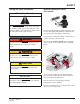
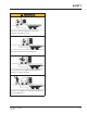
SAFETY Recognize Safety Information General Operational Safety Precautions Safety-Alert Symbol The Safety-Alert Symbol identifies important safety messages on equipment, safety signs, in manuals, or elsewhere. When you see this symbol, be alert to the possibility of personal injury or death. Follow the instructions in the safety message. Read and understand the operating instructions and become thoroughly familiar with the equipment and its controls before operating the dock leveler.
SAFETY Operational Safety Precautions Learn the safe way to operate this equipment. Read and understand the manufacturer’s instructions. If you have any questions, ask your supervisor. Stay clear of dock leveling device when transport vehicle is entering or leaving area. Chock/restrain all transport vehicles. Never remove the wheel chocks until loading or unloading is finished and truck driver has been given permission to drive away.
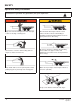
SAFETY Do not use dock leveling device if transport vehicle is too high or too low. Do not overload the dock leveling device. Do not operate any equipment while under the influence of alcohol or drugs. Do not leave equipment or material unattended on dock leveling device.
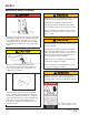
SAFETY Maintenance Safety Precautions ALWAYS disconnect electrical power source and ground wire before welding on dock leveler. DO NOT ground welding equipment to any hydraulic or electrical components of the dock leveler. Always ground to the dock leveler frame. Failure to follow these instructions may result in damage to dock leveler and/or serious personal injury or death. Hydraulic and electrical power must be OFF when servicing the equipment.
SAFETY Safety Decals Every 90 days (quarterly) inspect all safety labels and tags to ensure they are on the dock leveler and are easily legible. If any are missing or require replacement, please call 1-800-643-5424 for replacements. DANGER CRUSH HAZARD Maintenance prop must support leveler behind bar. Do not force maintenance prop forward of bar to support lip. Failure to comply will result in death or serious injury. Refer to owner’s/user’s manual for proper use.
OWNER’S/USER’S RESPONSIBILITIES 1. The owner/ user should recognize the inherent dangers of the interface between the loading dock and the transport vehicle. The owner/ user should, therefore, train and instruct all operators in the safe operation and use of the loading dock equipment in accordance with manufacturer’s recommendations and industry standards. Effective operator training should also focus on the owner’s/user’s company policies and operating conditions.
NOTES 4111-0012 — Aug 2012 April 2013 7
INTRODUCTION General Information Dock Leveler Stock Specifications LHP dock levelers are available in the following sizes, weight capacities, and options: Width 6 ft (1828.8 mm) 6-1/2 ft (1981.2 mm) 7 ft (2133.6 mm) Length 6 ft (1828.8 mm) 8 ft (2438 mm 10 ft (3048 mm) Congratulations on your choice of a Systems, Inc. dock leveler. This manual covers the LHP series hydraulic dock leveler. Designed by Systems, Inc. to be a marvel of simplicity and efficiency.
INTRODUCTION Component Identification A B C F D J E G H K A — Lip B — Platform C — Lip Cylinder D — Powerpack (Motor/Pump/Reservoir) E — Maintenance Prop F — Platform Cylinder G — Main Frame H — Lip Keepers (2 used) J — Full RangeToe Guard (4 used) K —Raise Button THEORY The LHP dock leveler uses a pressure operated valve block and single push-button operation for ease of use. The dock leveler can be operated remotely using the RAISE button (K) on the control panel .
INSTALLATION Prepare Pit A C B E 14” 10” D A—Distance (Pit Width) (Front and Rear) B— Distance (Dock Floor-to-Pit Floor) (All Four Corners) C— Distance (Pit Length) (Both Sides of Pit) D— Distance (Pit Corner- to- Corner) (Top, Bottom, and Both Sides) 1. Before lowering the dock leveler into the pit, the following must be performed: Post safety warnings and barricade the work area at dock level and ground level to prevent unauthorized use of the dock leveler before installation has been completed.
INSTALLATION Prepare Dock Leveler IMPORTANT A DO NOT remove the shipping bands (B) around the platform lip and leveler frame at this time. The shipping bands are needed to hold the leveler together during the installation process. 1. Remove any control panel and bumpers that may be banded to the frame of the dock leveler. DO NOT remove the shipping bands (B) around the platform lip and leveler frame at this time. IMPORTANT B A— Lifting Bracket (2 used) DO NOT overtighten the lifting bracket hardware.
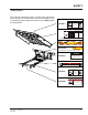
INSTALLATION Install Dock Leveler Shim Stacking Methods M N P Q A— Distance (Leveler Frame Height) B— Shim Locations (Under Rear Vertical Supports) C— Shim Location (Under Maintenance Prop,Lip Keepers, Main Cylinder) D—Dock Floor E— Rear Pit Curb Steel F— String 12 G— Rear Hinge frame Angle H— Distance (Dock floor-ToPit Floor) J— Distance (TOP of Shim to Dock Floor K— Shim Stack L— Dock Leveler Base Frame M — Pyramid (Preferred) N— Stepped (Acceptable) P— Offset (Not Acceptable) Q — Straight (Not Acc
INSTALLATION NOTE: Systems, Inc. dock levelers are designed with a nominal 1/2 in. (12.7 mm) shimming distance to allow for pit inconsistencies. 4. For all LHP models, put a 1/4 in. (6.6 mm) thick shim at locations (C and D) . 1. Determine height of shim stack (L) for each shim location (B) by performing the following: NOTE: A 1/4 in. (6.6 mm) thick shim at locations (C and D) is used only as a starting point. The final shim stack height will be determined after dock leveler is lowered into the pit. a.
INSTALLATION A— Front of Dock Pit B— Dock Leveler Frame C— Side Pit Curb Angle D— Gap [3/4 in. (19 mm) Minimum] 8. With rear hinge frame angle (F) tight against rear pit curb angle (G), perform/check the following: • Pry between the platform and rear hinge frame angle at locations (E) to make sure rear edge of platform is parallel to the rear hinge frame angle (F). • Gap (D) must exist equally along both sides of leveler so weather seal (if equipped) will not bind during dock leveler operation.
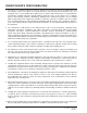
INSTALLATION IMPORTANT DO NOT grind or weld if hydraulic fluid or other flammable liquid is present on the surface to be ground or welded. DO NOT grind or weld if uncontained hydraulic fluid or other flammable liquid is present. Stray sparks can ignite spills or leaks near the work area. Always clean up the oil leaks and spills before proceeding with grinding or welding. Always keep a fire extinguisher of the proper type nearby when grinding or welding.
INSTALLATION A B D C A— Platform Joists B— Shim Locations (Under Platform Cylinder Trunnions) 14. Using an external lifting device (i.e., crane or fork truck) attached to the platform lifting brackets, slowly raise the platform. Check for binding as platform is being raised. 15. If binding occurs, lower the platform. Reposition leveler and/or add or remove shims as necessary. Slowly raise platform again. If platform still binds, contact Systems, Inc. Technical Services for further instructions. 16.
INSTALLATION Make sure the platform is properly supported in the raised position before entering the pit to finish weld the shims. Failure to do this may result in serious personal injury or death. 18. All model levelers: Install shims at locations (B) using the pyramid or stepped shimming method. Both platform cylinder trunnions must be solidly shimmed the entire length of the trunnion. Make sure the trunnions are level from side-to-side as well as from front-to-back. 19.
INSTALLATION Install Control Panel and Wiring The electrical power must be OFF prior to electrical installation. For maximum protection, use an OSHA approved locking device to lock out all power sources. Only the person installing the equipment should have the key to unlock the power source. A D B C Failure to follow these instructions may result in serious personal injury or death. DO NOT make any final electrical connections until all welding has been completed.
INSTALLATION Put New Dock Leveler Into Service 1. Disconnect the external lifting device and chains from the lifting brackets. 2. Check that the leveler is flush with the dock floor and that the platform lip contacts both lip keepers evenly. If an excessive transition exists between the dock floor and leveler and/or lip does not contact both lip keepers evenly, contact Systems, Inc. Technical Services for further instructions. 3. Install the dock bumpers as required. 7.
OPERATION Operating Instructions Stay clear of dock leveler when transport vehicle is entering or leaving dock area. 12 in. (305 mm) DO NOT move or use the dock leveler if anyone is under or in front of leveler. 12 in. (305 mm) Keep hands and feet clear of pinch points. Avoid putting any part of your body near moving parts. Failure to follow these instructions may result in severe personal injury or death. Only trained personnel should operate the dock leveler.
OPERATION Operating Instructions—Continued Ramp Loading/Unloading Instructions NOTE: If end unloading is required, see End Loading/Unloading Instructions on page 22. For ramp loading or unloading, the LHP dock leveler can be operated by using the RAISE button on the control panel. 1. Check to make sure transport vehicle is positioned squarely against dock bumpers. 5. Proceed with loading or unloading the transport vehicle. 6. If end loading is necessary, see End Loading/ Unloading Instructions on page 22.
OPERATION Operating Instructions—Continued End Loading/Unloading Instructions NOTE: If ramp loading is required, see Ramp Loading/Unloading Instructions on page 21. End loading or unloading can be done with the dock at the cross-traffic position or below-dock position, depending on the height of the transport vehicle bed. A 1. Check to make sure transport vehicle is positioned squarely against dock bumpers. 2. Instruct driver to remain at the dock until the loading or unloading process has been completed.
MAINTENANCE Service Dock Leveler Safely Side View F E A B C A— Tagout Device D B — Lockout Device C — Lockout Device D — Tagout Device E — Maintenance Prop F — Header Plate When service under the dock leveler is required, always lock all electrical disconnects in the OFF position after raising the platform and engaging the maintenance prop. Failure to do this may result in serious personal injury or death. Always stand clear of the dock leveler lip when working in front of the dock leveler.
MAINTENANCE Periodic Maintenance B A F C D A— Lip Area B— Platform Hinge Area C— Main Cylinder Pins D— Maintenance Prop Pivot Before performing any maintenance under the dock leveler, lock the electrical power source in OFF position and lock the maintenance prop in the service position using an approved locking device. (See Service Dock Leveler Safely in this section.) Failure to follow these instructions may result in serious personal injury or death.
MAINTENANCE Regular maintenance must be performed on a weekly and quarterly schedule. Follow All Safety Precautions Weekly Maintenance P Q N • Operate the dock leveler through the complete operating cycle to maintain lubrication. NOTE: To thoroughly inspect the platform hinge area, put the platform in the full below-dock position. • Inspect the platform hinge and the lip hinge areas. The hinge areas must be kept free of dirt and debris.
NOTES This page intentionally left blank 26 4111-0012 — Aug 2012 April 2013
ADJUSTMENTS Adjust Main Pressure Relief When service under the dock leveler is required, always lock all electrical disconnects in the OFF position after raising the platform and engaging the maintenance prop. Failure to do this may result in serious personal injury or death. A D C Always post safety warnings and barricade the work area at dock level and ground level to prevent unauthorized use of the dock leveler before maintenance is complete.
ADJUSTMENTS Adjust Lip Function 28 4111-0012 — Aug 2012 April 2013
ADJUSTMENTS When service under the dock leveler is required, always lock all electrical disconnects in the OFF position after raising the platform and engaging the maintenance prop. Failure to do this may result in serious personal injury or death. Always post safety warnings and barricade the work area at dock level and ground level to prevent unauthorized use of the dock leveler before maintenance is complete. Failure to do this may result in serious personal injury or death.
PARTS Electrical Components * Provide dock leveler serial number, voltage, phase, and options when calling or faxing controller orders.
PARTS Electrical Components 4111-0012 — Aug 2012 April 2013 31
PARTS A C B I D E J F H G 32 4111-0012 — Aug 2012 April 2013
PARTS LIPS ITEM QTY 25K 35K 40K 6.0 FOOT 1 A 1 1 B 2 C 2 D 1 E 1 F 1 16 DLIP-1250 DLIP-1256 DLIP-1259 18 DLIP-1251 DLIP-1257 DLIP-1260 20 DLIP-1252 DLIP-1258 6.5 FOOT DLIP-1261 16 DLIP-1262 DLIP-1268 DLIP-1271 18 DLIP-1263 DLIP-1269 DLIP-1272 20 DLIP-1264 DLIP-1270 7.0 FOOT DLIP-1273 16 DLIP-1274 DLIP-1280 DLIP-1283 18 DLIP-1275 DLIP-1281 DLIP-1284 20 DLIP-1276 DLIP-1282 DLIP-1285 113-264 PIN, LIP CYL DPLA-2101 6.0 FOOT LIP SHAFT DPLA-2102 6.
PARTS Hydraulic Components 34 4111-0012 — Aug 2012 April 2013
PARTS This page intentionally left blank 4111-0012 — Aug 2012 April 2013 35
Toe Guard / Weather Seal Options B C CC A K E F E G H J AR = As Required NOTE: Brush or track can be purchased separately as replacement parts. Contact factory for part numbers. Kits provide all parts / hardware to add Toe Guards or Weather Seal to an existing dock leveler. Weatherseal channel must be welded to leveler *Note, see Safety section (P.4). Pay special attention to removing grounds to motor anc control box before welding.
PARTS Weather Seal, Brush Style Item A B C CC D E F G H J K Quantity 2 2 2 2 2 4 1 1 2 1 1 Part Number DOTH-2818 DOTH-2824 DOTH-2820 DOTH-2822 DOTH-2041 DOTH-2207 See * Below See * Below DOTH-2131 See * Below See * Below Item Quantity Part Number A 1 C 1 * 1 4111-0012 — Aug 2012 April 2013 DOTH-2842 DOTH-2819 DOTH-2187 DOTH-2843 DOTH-2850 DOTH-2821 DOTH-2820 DOTH-2851 DKIT-9178 DKIT-9179 DKIT-9180 DKIT-9181 Description Channel, Weather Seal, 84” T-Rubber, Weather Seal, 84” Extrusion, Brush Wea
Control Box A B D 7-1/8 Hole centers C 4.50 3.50 O P E R AT I N G ! DANGER INSTRUCTIONS POWERED DOCK LEVELERS ! Read and follow all instructions, warnings and maintenance schedules in the manual and on placards. ! Operation and servicing of dock leveler is restricted to trained personnel. E NORMAL OPERATION 1 Raise the platform by depressing and holding the RAISE button. 2 Hold the RAISE button until the lip is fully extended, then release the RAISE button.
PARTS This page intentionally left blank 4111-0012 — Aug 2012 April 2013 39
PARTS This page intentionally left blank 40 4111-0012 — Aug 2012 April 2013
MISCELLANEOUS Customer Information A A NOTE: Refer to illustration for left/right orientation of dock leveler. The model/serial number decal (A) is located on the right platform joist near the front (lip) of dock leveler. Dock Leveler Information Model ___________________________________ Serial No. ________________________________ Systems, Inc., Job No. ______________________ When you receive your LHP dock leveler, write down the dock leveler model and serial number in the form provided.
STANDARD PRODUCT WARRANTY SYSTEMS, INC. warrants that its products will be free from defects in design, materials and workmanship for a period of one (1) year from the date of shipment. All claims for breach of this warranty must be made within 30 days after the defect is or can with reasonable care, be detected. In no event shall any claim be made more than 30 days after this warranty has expired.