HED SERIES Hydraulic EOD Dock Leveler Owner’s/User’s Manual DLM • Division of Systems, Inc. • W194 N11481 McCormick Drive • Germantown, WI 53022 800.643.5424 • fax: 262.255.5917 • www.docksystemsinc.com • techservices@docksystemsinc.com Printed in U.S.A. Copyright © 2009 Manual No. 4111-0027 Sept.
Table of Contents Page Safety Recognize Safety Information.............................................................. General Operational Safety Precautions............................................. Operational Safety Precautions............................................................ Maintenance Safety Precautions.......................................................... Safety Decals..........................................................................................
SAFETY Recognize Safety Information Safety-Alert Symbol The Safety-Alert Symbol identifies important safety messages on equipment, safety signs, in manuals, or elsewhere. When you see this symbol, be alert to the possibility of personal injury or death. Follow the instructions in the safety message. General Operational Safety Precautions Read and understand the operating instructions and become thoroughly familiar with the equipment and its controls before operating the dock leveler.
SAFETY Operational Safety Precautions Learn the safe way to operate this equipment. Read and understand the manufacturer’s instructions. If you have any questions, ask your supervisor. Stay clear of dock leveling device when freight carrier is entering or leaving area. Chock/restrain all freight carriers. Never remove the wheel chocks until loading or unloading is finished and truck driver has been given permission to drive away.
SAFETY Do not use dock leveling device if freight carrier is too high or too low. Do not overload the dock leveling device. Do not operate any equipment while under the influence of alcohol or drugs. Do not leave equipment or material unattended on dock leveling device. Manual No. 4111-0027 Sept.
SAFETY Maintenance Safety Precautions ALWAYS disconnect electrical power source and ground wire before welding on dock leveler. DO NOT ground welding equipment to any hydraulic or electrical components of the dock leveler. Always ground to the dock leveler frame. Failure to follow these instructions may result in damage to dock leveler and/or serious personal injury or death. Hydraulic and electrical power must be OFF when servicing the equipment.
SAFETY Safety Decals SAFETY INFORMATION DANGER Unsupported dock leveler ramps can lower unexpectedly. 2 Before allowing vehicle to leave the dock always: Ensure that no equipment, material or people are on the dock leveler. Return the dock leveler to its stored position at dock level. Failure to follow posted instructions will result in death or serious injury. Unsupported dock leveler ramps can lower unexpectedly.
OWNER’S/USER’S RESPONSIBILITIES 1. The owner/ user should recognize the inherent dangers of the interface between the loading dock and the transportation vehicle. The owner/ user should, therefore, train and instruct all operators in the safe operation and use of the loading dock equipment in accordance with manufacturer’s recommendations and industry standards. Effective operator training should also focus on the owner’s/user’s company policies and operating conditions.
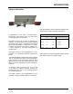
INTRODUCTION General Information HED Series Edge-of-Dock levelers are available in the following sizes, weight capacities, and options: Congratulations on your choice of a DLM Edge-ofDock leveler. This manual covers the HED series mechanical Edge-of-Dock levelers. Designed by DLM to be a marvel of simplicity and efficiency, your dock leveler, when properly installed, will provide many years of trouble-free performance with an absolute minimum of maintenance.
INTRODUCTION Component Identification A F B E D C G J H A — Lip Plate B —Center Plate C — Safety Prop D — Powerpack (Motor/Pump/Reservoir) E — Hinge Area F — Lip Cylinder G — Main Hoist Cylinder H — Bumper Blocks (2 used) J —Raise Button THEORY The HED Edge-of-Dock leveler uses hydraulic pressure and single push-button operation for ease of use. Platform (B) is raised by pushing and holding the RAISE button (J). This activates an electric motor (D) which, in turn, drives a hydraulic pump.
INTRODUCTION This page intentionally left blank Manual No. 4111-0027 Sept.
INSTALLATION INSTALLATION DETAILS ANCHOR BOLT OR PLUG WELD Post safety warnings and barricade the work area at dock level and ground level to prevent unauthorized use of the dock leveler before installation has been completed. Failure to follow the installation instructions can result in damage to dock leveler, the facilities, and/ or serious personal injury or death. Only trained installation professionals with the proper equipment should install this product.
INSTALLATION IMPORTANT DO NOT connect the dock leveler electrical wiring and ground connections until all welding has been completed. DO NOT ground welding equipment to any hydraulic or electrical components of the dock leveler. Always ground welding equipment to the dock leveler frame, NEVER to the platform. Failure to follow these instructions may damage the motor, hoist cylinder, wiring, and/or control panel. IMPORTANT DO NOT weld continuously along the full length of the base plate.
INSTALLATION H.E.D. Installation Instructions - Flush Mount - Weld On A flush mount weld on application is used when an 8” wide (minimum) embed channel is securely anchored into the concrete at the dock edge, and the dock height is adequate. Installation Steps: 1. Remove all existing bumper material and protruding objects from dock edge. Clean and sweep dock edge free of debris and flammable chemicals before installing unit. 2.
Manual No. 4111-0027 Sept. 2009 May 2012 DESCRIPTION Top of base plate and bumper cover plate to be flush with top of dock floor and embedded channel Apply continuous bevel weld across both bumpers and length of base plate. NOTE 1 2 Junction Box Securely block or support ramp and lip when in vertical positions. Lack of proper bracing can result in ramp dropping during adjustment or installation causing personal injury or damage to unit.
INSTALLATION H.E.D. Installation Instructions - RampMount - Weld/Bolt On A ramp mount-weld on application is used when adequate dock steel is securely anchored in the concrete at the dock edge, but the existing dock height is too low and the dock leveler must be installed above this height to correct this situation. Installation Steps: 1. Remove all existing bumper material and protruding objects from dock edge. Clean and sweep dock edge free of debris and flammable chemicals before installing unit.
Manual No. 4111-0027 Sept. 2009 May 2012 DESCRIPTION Top of base plate and bumper cover plate to be flush with top of ramp plate. Apply continuous bevel weld across both bumpers and length of base plate. To figure ramp plate length, need 12” ramp for every 1-1/2” of rise to ramp. NOTE 1 2 3 Junction Box Securely block or support ramp and lip when in vertical positions. Lack of proper bracing can result in ramp dropping during adjustment or installation causing personal injury or damage to unit.
INSTALLATION H.E.D. Installation Instructions - Flush Mount - Bolt On A flush mount bolt on application is used when there is no steel on dock edge, and the dock height is adequate. Additional steel ramp plate and bolting is required with this type of installation. Installation Steps: 1. Remove all existing bumper material and protruding objects from dock edge. Clean and sweep dock edge free of debris and flammable chemicals before installing unit. 2. 3.
INSTALLATION Junction Box Securely block or support ramp and lip when in vertical positions. Lack of proper bracing can result in ramp dropping during adjustment or installation causing personal injury or damage to unit. Manual No. 4111-0027 Sept. 2009 May 2012 NOTE DESCRIPTION 1 Top of base plate and bumper cover plate to be flush with top of ramp plate. 2 Apply continuous bevel weld across both bumpers and length of base plate.
INSTALLATION H.E.D. Installation Instructions - Ramp Mount - Weld On w/Formed Angle A ramp mount-weld on used with a formed angle application is used when dock edge is damaged, there is no dock steel securely anchored into the concrete, and the dock height is too low and the leveler must be installed above this height to correct this situation. Installation Steps: 1. Remove all existing bumper material and protruding objects from dock edge.
2X Manual No. 4111-0027 Sept. 2009 May 2012 DESCRIPTION Top of base plate and bumper cover plate to be flush with top of ramp plate. Apply continuous bevel weld across both bumpers and length of base plate. To figure ramp plate length, need 12” ramp for every 1-1/2” of rise to ramp. To install formed angle, see formed angle installation instructions. NOTE 1 2 3 4 Junction Box Securely block or support ramp and lip when in vertical positions.
INSTALLATION H.E.D. Installation Instructions - Formed Angle A formed angle is used when there is no existing dock steel and concrete at the dock edge has been damaged. The formed angle is required to rebuild the damaged concrete edge for a proper installation if the dock height is adequate. Installation Steps: 1. Remove all existing bumper material and protruding objects from dock edge. Clean and sweep dock edge free of debris and flammable chemicals before installing unit. 2.
Manual No. 4111-0027 Sept.
INSTALLATION H.E.D. Installation Instructions - Ramp and Face Plate A ramp mount requiring a face plate application is used when there is no existing dock steel and the concrete at the dock edge has been damaged. The dock height can be low, high, or adequate for this application, however, the face plate and ramp plate are required to rebuild the damaged concrete edge. Installation Steps: 1. Remove all existing bumper material and protruding objects from dock edge.
Manual No. 4111-0027 Sept.
INSTALLATION CHECK LIST E.O.D. Installation Checklist Date: __________ Order No.: __________ Serial Number:______________ Installer: ____________________________ Customer Name: _____________________ Address: ____________________________ City/State: ___________________________ Zip: __________ Phone: _________________ 1. Unit is properly aligned and installed properly. 2. All welding has been fully completed. 3. Welding slag has been removed. 4.
INSTALLATION This page intentionally left blank Manual No. 4111-0027 Sept.
INSTALLATION Install Control Panel and Wiring The electrical power must be OFF prior to electrical installation. For maximum protection, use an OSHA approved locking device to lock out all power sources. Only the person installing the equipment should have the key to unlock the power source. Failure to follow these instructions may result in serious personal injury or death. DO NOT make any final electrical connections until all welding has been completed.
INSTALLATION Put New Dock Leveler Into Service 1. Disconnect the external lifting device 2. Install the dock bumpers as required. 3. Turn the main electrical power ON. 4. Raise the leveler platform fully by pushing and holding the RAISE button. NOTE: The platform of a properly operating dock leveler will automatically stop rising when it reaches its full raised height, at which point, the lip extends. 5. Release the RAISE button to lower the platform.
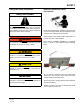
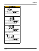
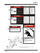
OPERATION Operating Instructions Stay clear of dock leveler when freight carrier is entering or leaving dock area. 5 in. (127 mm) DO NOT move or use the dock leveler if anyone is under or in front of leveler. Keep hands and feet clear of pinch points. Avoid putting any part of your body near moving parts. Failure to follow these instructions may result in severe personal injury or death. Only trained personnel should operate the dock leveler. DO NOT use a broken or damaged dock leveler.
OPERATION 1. Make certain all equipment and personnel are clear of leveler before operation. 3. Always remove any end load while leveler is in stored position. (Figure 1). 2. The truck should be firmly against the bump blocks and wheels chocked before operation of the leveler. 4. Press and hold “RAISE” (A) button until leveler extends fully (Figure 3). 5. Release button. Leveler will lower to truck bed (Figure 4). 6.
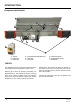
MAINTENANCE Periodic Maintenance A D B C S Y S T E M S, P O W E R A M P D L M I N C. L o a d i n g D o c k E q u i p m e n t NL-X MAINTENANCE PROP DRAWN BY SR TOLERANCES (UNLESS OTHERWISE NOTED) FRACTIONAL: `1/32" CHECKED BY DATE 8/6/2009 DRAWING NO. HED6620-15 Maintena DECIMAL: .00 = `.01" .000 = `.
MAINTENANCE Periodic Maintenance N P Q Regular maintenance must be performed on a weekly and quarterly schedule. Weekly Maintenance • Operate the dock leveler through the complete operating cycle to maintain lubrication. NOTE: To thoroughly inspect the platform hinge area, put the platform in the full below-dock position. • M Inspect the platform hinge and the lip hinge areas. The hinge areas must be kept free of dirt and debris.
NOTES This page intentionally left blank 32 Manual No. 4111-0027 Sept.
ADJUSTMENTS Adjust Main Pressure Relief When service under the dock leveler is required, always lock all electrical disconnects in the OFF position after raising the platform and engaging the maintenance prop. Failure to do this may result in serious personal injury or death. A D C Always post safety warnings and barricade the work area at dock level and ground level to prevent unauthorized use of the dock leveler before maintenance is complete.
ADJUSTMENTS Adjust Lip Function 1. Raise platform fully and engage the maintenance prop in the service position. Allow platform to rest on the prop so the lip will fully fold until it contacts the lip stops. 2. Turn OFF all electrical power to the dock leveler. Attach safety lockout and tagout devices. When service under the dock leveler is required, always lock all electrical disconnects in the OFF position after raising the platform and engaging the maintenance prop.
ADJUSTMENTS This page intentionally left blank Manual No. 4111-0027 Sept.
36 * Provide dock leveler serial number, voltage, phase, and options when calling or faxing controller orders. Field Wire 18 gauge min. Field Wire 18 gauge min. ELECTRICAL 1 Phase Manual No. 4111-0027 Sept.
Manual No. 4111-0027 Sept. 2009 May 2012 * Provide dock leveler serial number, voltage, phase, and options when calling or faxing controller orders. Field Wire 18 gauge min. Field Wire 18 gauge min.
TROUBLESHOOTING Before performing the detailed troubleshooting procedures, check the following items first: • Make sure the correct voltages are preset at the proper locations inside the control panels Symptom Possible Cause Solution Motor overload device Reset overload relay (three-phase). Determine cause tripped or fuse blown. of overload. Check voltage at starter or relay coil. Platform does not rise. Motor does not energize.
TROUBLESHOOTING Symptom Unit raises but the lip plate will not retract. Solution Turn sequence valve clockwise approximately 1/4 turn and retest unit. If the lip plate still will not retract, repeat the above adjustment until unit operates properly. Unit raises but the lip plate will not extend. The unit raises slowly, the motor is extremely Check the fluid level in power unit reservoir, if low, add fluid and noisy, and the hydraulic hoses are vibrating.
PARTS 14 11 9 13 7 12 16 15 4 10 17 1 5 2 6 8 3 7 15 23 24 25 21 22 18 19 20 26 27 29 28 ITEM 1 40 QTY SIZE/CAPACITY DESCRIPTION PART NUMBER (15” LIP) PART NUMBER (17” LIP) 1 6620/25 Lip Plate & Hinge Assembly DOTH-4100 DOTH-4111 1 6630 Lip Plate & Hinge Assembly DOTH-4104 DOTH-4195 1 6635 Lip Plate & Hinge Assembly DOTH-4129 DOTH-4133 1 7220/25 Lip Plate & Hinge Assembly DOTH-4106 DOTH-4166 1 7230 Lip Plate & Hinge Assembly DOTH-4114 DOTH-4172 1 7235 Lip
PARTS QTY SIZE/CAPACITY DESCRIPTION PART NUMBER (15” LIP) 1 6620/25 Center Plate & Hinge Assembly DOTH-4200 1 6630 Center Plate & Hinge Assembly DOTH-4208 1 6635 Center Plate & Hinge Assembly DOTH-3231 1 7220/25 Center Plate & Hinge Assembly DOTH-4212 1 7230 Center Plate & Hinge Assembly DOTH-4220 1 7235 Center Plate & Hinge Assembly DOTH-4218 1 7820/25 Center Plate & Hinge Assembly DOTH-4222 1 7830 Center Plate & Hinge Assembly DOTH-4223 1 8420/25 Center Plate & Hinge
PARTS DBBS-3550 Complete 18” Projection Bumper Assembly ITEM QTY PART NUMBER DESCRIPTION 1 1 DOTH-3556 18” Proj. x 12” BB Weldment (HED) SIZE 2 1 DOTH-3505 Rubber - TUF-Cord 4 X 12 X 13 3 4 DOTH-2056 Hex HEad Cap Screw 7/16-14 UNC X 3-1/4 4 4 DOTH-2210 Washer - Flat - Zinc Plated 1/2” Dia. 5 4 DOTH-2208 Washer - Flat 1/2” Dia. 6 4 DOTH-2129 Nylon Lock Nut 7/16-14 UNC DKIT-3541 Bumper with Hardware * BILL OF MATER ITEM QTY PART NO. DESCRIPTION 1 1 DOTH-3556 18" PROJ.
PARTS This Page Intentionally Left Blank Manual No. 4111-0027 Sept.
MISCELLANEOUS This page intentionally left blank 44 Manual No. 4111-0027 Sept.
MISCELLANEOUS Customer Information A NOTE: The model/serial number decal (A) is located on the right platform joist near the front (lip) of dock leveler. When you receive your HED-series Edge-of-Dock leveler, write down the dock leveler model and serial number in the form provided. This will help ensure safe keeping of the numbers in the event the model/serial number decal (A) becomes lost or damaged. Also, write down Systems, Inc.
STANDARD PRODUCT WARRANTY SYSTEMS, INC. warrants that its products will be free from defects in design, materials and workmanship for a period of one (1) year from the date of shipment. All claims for breach of this warranty must be made within 30 days after the defect is or can with reasonable care, be detected. In no event shall any claim be made more than 30 days after this warranty has expired.