DL-NL-TS SERIES EOD Dock Leveler Owner’s/User’s Manual DLM • Division of Systems, Inc. • W194 N11481 McCormick Drive • Germantown, WI 53022 800.643.5424 • fax: 262.257.7399 • www.docksystemsinc.com • techservices@docksystemsinc.com Printed in U.S.A. Copyright © 2011 Manual No.
Table of Contents Page Safety Recognize Safety Information..................................................................1 General Operational Safety Precautions.................................................1 Operational Safety Precautions...............................................................2 Maintenance Safety Precautions.............................................................4 Safety Decals...........................................................................................
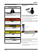
SAFETY Recognize Safety Information Safety-Alert Symbol The Safety-Alert Symbol identifies important safety messages on equipment, safety signs, in manuals, or elsewhere. When you see this symbol, be alert to the possibility of personal injury or death. Follow the instructions in the safety message. General Operational Safety Precautions Read and understand the operating instructions and become thoroughly familiar with the equipment and its controls before operating the dock leveler.
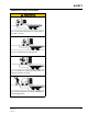
SAFETY Operational Safety Precautions Learn the safe way to operate this equipment. Read and understand the manufacturer’s instructions. If you have any questions, ask your supervisor. Stay clear of dock leveling device when freight carrier is entering or leaving area. Chock/restrain all freight carriers. Never remove the wheel chocks until loading or unloading is finished and truck driver has been given permission to drive away.
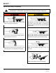
SAFETY Operational Safety Precautions Do not use dock leveling device if freight carrier is too high or too low. Do not overload the dock leveling device. Do not operate any equipment while under the influence of alcohol or drugs. Do not leave equipment or material unattended on dock leveling device. Manual No.
SAFETY Maintenance Safety Precautions To put handle into maintenance prop position, remove bolt and locknut at base of handle assembly. Pull handle out of roller arm assembly and place into maintenance prop receiver, if equipped. Post safety warnings and barricade the work area at dock level and ground level to prevent unauthorized use of the dock leveler before installation has been completed. ALWAYS stand clear of dock leveler lip when working in front of the dock leveler.
Unsupported dock leveler ramps can lower unexpectedly. 2 manual. sides of moving dock leveler. 2. Use of dock leveler restricted to 8. Never use damaged or trained operators malfunctioning dock leveler. Report 3. Always chock trailer wheels or problems immediately to supervisor. engage truck restraint before Before allowing vehicle to leave operating dock leveler or beginning to Maintenance/Service load or unload. 1. Read and follow all instructions, the dock always: 4.
OWNER’S/USER’S RESPONSIBILITIES 1. The owner/ user should recognize the inherent dangers of the interface between the loading dock and the transportation vehicle. The owner/ user should, therefore, train and instruct all operators in the safe operation and use of the loading dock equipment in accordance with manufacturer’s recommendations and industry standards. Effective operator training should also focus on the owner’s/user’s company policies and operating conditions.
NOTES This page intentionally left blank Manual No.
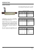
INTRODUCTION General Information DL-NL-TS Series Edge-of-Dock levelers are available in the following sizes, weight capacities, and options: Dimensions and Capacities Model # Congratulations on your choice of a DLM Edge-ofDock leveler. This manual covers the DL-NL-TS series mechanical Edge-of-Dock levelers. Designed by DLM to be a marvel of simplicity and efficiency, your dock leveler, when properly installed, will provide many years of trouble-free performance with an absolute minimum of maintenance.
INSTALLATION INSTALLATION DETAILS 50 INCH PREFERRED Only trained installation professionals with the proper equipment should install this product. IMPORTANT DO NOT remove the shipping bands around the dock leveler lip until instructed to do so. Manual No. 4111-0025 March 2011 May 2012 Post safety warnings and barricade the work area at dock level and ground level to prevent unauthorized use of the dock leveler before installation has been completed.
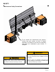
INSTALLATION E.O.D. Installation Instructions - Flush Mount - Weld On Follow all safety precautions prior to installation. A flush mount weld on application is used when an 8” wide (minimum) embed channel is securely anchored into the concrete at the dock edge, and the dock height is adequate. Installation Steps: 1. Remove all existing bumper material and protruding objects from dock edge. Clean and sweep dock edge free of debris and flammable chemicals before installing unit. 2.
Manual No. 4111-0025 March 2011 May 2012 DESCRIPTION Top of base plate and bumper cover plate to be flush with top of dock floor and embedded channel Apply continuous bevel weld across both bumpers and length of base plate. NOTE 1 2 Securely block or support ramp and lip when in vertical positions. Lack of proper bracing can result in ramp dropping during adjustment or installation causing personal injury or damage to unit.
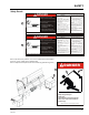
INSTALLATION E.O.D. Installation Instructions - RampMount - Weld/Bolt On Follow all safety precautions prior to installation. A ramp mount weld on application is used when adequate dock steel is securely anchored in the concrete at the dock edge, but the existing dock height is too low and the dock leveler must be installed above this height to correct this situation. Installation Steps: 1. Remove all existing bumper material and protruding objects from dock edge.
Manual No. 4111-0025 March 2011 May 2012 DESCRIPTION Top of base plate and bumper cover plate to be flush with top of ramp plate. Apply continuous bevel weld across both bumpers and length of base plate. To figure ramp plate length, need 12” ramp for every 1-1/2” of rise to ramp. NOTE 1 2 3 Securely block or support ramp and lip when in vertical positions. Lack of proper bracing can result in ramp dropping during adjustment or installation causing personal injury or damage to unit.
INSTALLATION E.O.D. Installation Instructions - Flush Mount - Bolt On Follow all safety precautions prior to installation. A flush mount bolt on application is used when there is no steel on dock edge, and the dock height is adequate. Additional steel ramp plate and bolting is required with this type of installation. Installation Steps: 1. Remove all existing bumper material and protruding objects from dock edge. Clean and sweep dock edge free of debris and flammable chemicals before installing unit. 2.
INSTALLATION of lever, with the unit raised and secured in the maintenance position, loosen jam nut on the underside of the linkage pin. To start allow about 3/4” to 1” of threads between top of jam nut and linkage pin. Using an open faced wrench, hold locknut on inside of spring while tightening threaded bolt until washer on top side of spring closes up tight to ram nut. Test operation of unit. Further adjust spring tension if needed by advancing jam nut toward linkage pin and tightening threaded rod.
INSTALLATION E.O.D. Installation Instructions - Ramp Mount - Weld On w/Formed Angle Follow all safety precautions prior to installation. A ramp mount-weld on used with a formed angle application is used when dock edge is damaged, there is no dock steel securely anchored into the concrete, and the dock height is too low and leveler must be installed above this height to correct this situation. Installation Steps: 1. Remove all existing bumper material and protruding objects from dock edge.
Manual No. 4111-0025 March 2011 May 2012 DESCRIPTION Top of base plate and bumper cover plate to be flush with top of ramp plate. Apply continuous bevel weld across both bumpers and length of base plate. To figure ramp plate length, need 12” ramp for every 1-1/2” of rise to ramp. To install formed angle, see formed angle installation instructions. NOTE 1 2 3 4 Securely block or support ramp and lip when in vertical positions.
INSTALLATION E.O.D. Installation Instructions - Formed Angle Follow all safety precautions prior to installation. A formed angle is used when there is no existing dock steel and concrete at the dock edge has been damaged. The formed angle is required to rebuild the damaged concrete edge for a proper installation if the dock height is adequate. Installation Steps: 1. Remove all existing bumper material and protruding objects from dock edge.
Manual No.
INSTALLATION E.O.D. Installation Instructions - Ramp and Face Plate Follow all safety precautions prior to installation. A ramp mount requiring a face plate application is used when there is no existing dock steel and the concrete at the dock edge has been damaged. The dock height can be low, high, or adequate for this application, however, the face plate and ramp plate are required to rebuild the damaged concrete edge. Installation Steps: 1.
Manual No.
INSTALLATION - CHECK LIST E.O.D. Installation Checklist Date: __________ Order No.: __________ Serial Number:______________ Installer: ____________________________ Customer Name: _____________________ Address: ____________________________ City/State: ___________________________ Zip: __________ Phone: _________________ 1. Unit is properly aligned and installed properly. 2. All welding has been fully completed. 3. Welding slag has been removed. 4.
OPERATION OPERATING INSTRUCTIONS FOR DL-SERIES 1. With leveler in stored position, back the truck into position against the bump blocks. 2. Truck should be chocked before operation of leveler. 3. While standing behind the unit, use lifting hook to pull back and up on rivet OR engage on the notch until leveler is cocked. 4. Then actuate the leveler by placing the lifting hook into lip plate notch and manually lifting the hook until the lip plate section extends over the truck bed.
OPERATION OPERATING INSTRUCTIONS FOR NL & TS SERIES 1. Grasp the captured operating handle and raise to its full extended length. 3. Push forward on operating handle against the rivet, rotating leveler out onto truck. 2. Move handle toward you, rotating center plate back past vertical. Lip plate extend link arm will engage at this time. 4. Return handle to stored position. 5. To remove leveler from truck repeat step number one until the lip clears the bed of the trailer.
MAINTENANCE PERIODIC MAINTENANCE When maintenance is to be performed in front of the dock leveler, support the lip with the handle in the maintenance prop position OR by other means. Always post safety warnings and barricade the work area at dock level and ground level to prevent unauthorized use of the dock leveler before maintenance is complete. Failure to do this may result in serious personal injury or death.
TROUBLESHOOTING Symptom Unit does not operate properly Extended link arm does not latch out lip or unlatch Possible Cause Debris impacted on or around the leveler Clean out debris on or around leveler Insufficient lubrication Lubricate leveler Excessive weight on top of deck Remove weight from deck.
PARTS 5 DL-X Series 6 1 5 2 9 6 10 4 11 7 3 S 4 Y S T E M S, P O W E R A D I N C.
PARTS NL-X Series 28 Manual No.
PARTS ITEM 1 2 3 4 QTY SIZE/CAPACITY DESCRIPTION PART NUMBER (15”) LIP PART NUMBER (17”LIP) 1 6620/25 Lip Plate & Hinge Assembly DOTH-4047 DOTH-4048 1 6630 Lip Plate & Hinge Assembly DOTH-4049 DOTH-4050 1 6635 Lip Plate & Hinge Assembly DOTH-4051 DOTH-4052 1 7220/25 Lip Plate & Hinge Assembly DOTH-4053 DOTH-4054 1 7230 Lip Plate & Hinge Assembly DOTH-4055 DOTH-4056 1 7235 Lip Plate & Hinge Assembly DOTH-4057 DOTH-3167 1 7820/25 Lip Plate & Hinge Assembly DOTH-4058
PARTS TS Series 6 16 15 14 12 2 11 4 1 5 9 13 8 3 4 18 19 20 S Y S L o a d i n 17 NL-RR MO DRAWN BY 21 SR TOLERANCES 10 (UNLESS OTHERWISE NOTED) FRACTIONAL: `1/32" DECIMAL: .00 = `.01" .000 = `.005" 7 30 ANGULAR: `1~ This print is the property of Systems, I patent and other rights, including exclu not convey any permission to reprodu granted only by written authorization s Manual No.
PARTS ITEM QTY SIZE/CAPACITY DESCRIPTION PART NUMBER (15”) LIP PART NUMBER (17”LIP) 1 6620/25 Lip Plate & Hinge Assembly DOTH-4068 DOTH-4069 1 6630 Lip Plate & Hinge Assembly DOTH-4070 DOTH-4071 1 6635 Lip Plate & Hinge Assembly DOTH-4072 DOTH-4073 1 7220/25 Lip Plate & Hinge Assembly DOTH-4074 DOTH-4075 1 7230 Lip Plate & Hinge Assembly DOTH-4076 DOTH-4077 1 7235 Lip Plate & Hinge Assembly DOTH-4078 DOTH-4079 1 7820/25 Lip Plate & Hinge Assembly DOTH-4080 DOTH-4081
PARTS DOTH-3618 Replacement Extension Spring Kits (Includes all parts listed below) Item Quantity Part Number 1 2 3 4 5 6 7 8 9 10 1 2 4 2 1 2 2 4 2 2 Description DOTH-3620 Bar - Lip linkage DOTH-2061 1-1/2” Shoulder Bolt DOTH-2131 Nylon Lock Nut DOTH-3621 Bar - Base Linkage DOTH-2347 Pin - Linkage DOTH-2390 Roll Pin DOTH-2520 Spring, Extension, Reg.
PARTS DOTH-3630 Replacement Extension Spring Kits (Includes all parts listed below) Item Quantity Part Number 1 2 3 4 5 6 7 8 9 10 1 2 4 2 1 2 2 4 2 2 Description DOTH-3620 Bar - Lip linkage DOTH-2061 1-1/2” Shoulder Bolt DOTH-2131 Nylon Lock Nut DOTH-3621 Bar - Base Linkage DOTH-2347 Pin - Linkage DOTH-2390 Roll Pin DOTH-2521 Spring, Extension, Reg.
PARTS DOTH-3675 Torsion Spring Kit (Includes all parts listed below) Item Quantity Part Number 1 2 3 4 5 6 7 8 9 10 11 12 1 1 1 1 1 1 3 1 1 2 2 2 Description DOTH-3305 L&R Gusset Assembly w/Bearing DOTH-3327 HL Model Gusset w/Guide DOTH-3679 HL Torsion Tube Assembly DOTH-3676 HL Torsion Bar Assembly DOTH-2509 Spring Torsion DOTH-3316 Bar-Pivot DOTH-2033 HHCS - Grade 2 - Zinc Plated DOTH-2121 Nylon Lock Nut DOTH-3682 HL Plate Locking Torsion DOTH-3617 Bar - 6630 L-Linkage DOTH-2061 1-1/2” Shoulder Bolt DO
PARTS CURRENT VS 2005 and Older Item Quantity Part Number 1 1 DOTH-3730 2 1 DOTH-3744 3 1 DOTH-3585 4 1 DOTH-3586 Manual No.
PARTS HANDLE OPTIONS Item Quantity Part Number 1 2 3 4 36 1 1 1 1 Description DOTH-3752 NL Handle Assembly (Tube) DOTH-3769 NL Handle Assembly (Solid) DOTH-3691 NLII Handle Assembly (Formed) DOTH-3694 NLIII Handle Assembly Manual No.
PARTS OPERATING LINK OPTIONS Item Quantity Part Number 1 2 1 1 DOTH-3726 DOTH-3696 3 1 DOTH-3697 4 1 DOTH-2449 Description NL Operating Link Assembly NLIII Operating Link Assembly Operating Link Assembly for all 35K units (not shown) Roller Bearing ITEM QTY PART NO. 1 1 DOTH-3726 NL OPERA 2 1 DOTH-3696 NLIII OPER 3 1 DOTH-3834 NLIII ROLL PIPE 4 2 1 Manual No.
Item Quantity Part Number 1 1 4 4 4 4 2 DOTH-3537 12” BB Weldment DOTH-3505 Rubber - Tuf-Cord DOTH-2056 Hex Head Cap Screw DOTH-2210 Wahser - Flat - Zinc Plated DOTH-2208 Washer - Flat DOTH-2129 Nylon Lock Nut DBBS-3506 15” Projection x 18” high (option) 1 4 6 5 4 3 2 1 IT EM 1 Q TY 1 2 3 4 5 6 Description P D AR O D T T 4 D OT H-3 NO 4 O H D T -3 53 .
QT Y PA 1 DO RT N 2 O T DO H-35 .
MISCELLANEOUS This page intentionally left blank 40 Manual No.
MISCELLANEOUS Customer Information A NOTE: The model/serial number decal (A) is located on the outboard side of the outer most (LH) gusset or base plate. When you receive your DL, NL or TS series Edgeof-Dock leveler, write down the dock leveler model and serial number in the form provided. This will help ensure safe keeping of the numbers in the event the model/serial number decal (A) becomes lost or damaged.
STANDARD PRODUCT WARRANTY SYSTEMS, INC. warrants that its products will be free from defects in design, materials and workmanship for a period of one (1) year from the date of shipment. All claims for breach of this warranty must be made within 30 days after the defect is or can with reasonable care, be detected. In no event shall any claim be made more than 30 days after this warranty has expired.