EH SERIES Dock Leveler Owner’s Manual POWERAMP • Division of Systems, Inc. • W194 N11481 McCormick Drive • Germantown, WI 53022 800.643.5424 • fax: 262.257.7399 • www.docksystemsinc.com • techservices@docksystemsinc.com Printed in U.S.A. Copyright © 2003 Manual No.
Table of Contents Page Safety Recognize Safety Information . . . . . . . . . . . . . . . . . . . . . . . . . . . . . . . 1 General Operational Safety Precautions . . . . . . . . . . . . . . . . . . . . . . 1 Operational Safety Precautions . . . . . . . . . . . . . . . . . . . . . . . . . . . . . 2 Maintenance Safety Precautions . . . . . . . . . . . . . . . . . . . . . . . . . . . . 4 Safety Decals . . . . . . . . . . . . . . . . . . . . . . . . . . . . . . . . . . . . . . . . . . . .
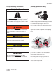
SAFETY Recognize Safety Information General Operational Safety Precautions Safety-Alert Symbol The Safety-Alert Symbol identifies important safety messages on equipment, safety signs, in manuals, or elsewhere. When you see this symbol, be alert to the possibility of personal injury or death. Follow the instructions in the safety message. Read and understand the operating instructions and become thoroughly familiar with the equipment and its controls before operating the dock leveler.
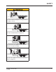
SAFETY Operational Safety Precautions Learn the safe way to operate this equipment. Read and understand the manufacturer's instructions. If you have any questions, ask your supervisor. Stay clear of dock leveling device when freight carrier is entering or leaving area. Chock/restrain all freight carriers. Never remove the wheel chocks until loading or unloading is finished and truck driver has been given permission to drive away.
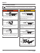
SAFETY Do not use dock leveling device if freight carrier is too high or too low. Do not overload the dock leveling device. Do not operate any equipment while under the influence of alcohol or drugs. Do not leave equipment or material unattended on dock leveling device.
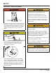
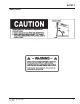
SAFETY Maintenance Safety Precautions ALWAYS disconnect electrical power source and ground wire before welding on dock leveler. DO NOT ground welding equipment to any hydraulic or electrical components of the dock leveler. Always ground to the dock leveler frame. Failure to follow these instructions may result in damage to dock leveler and/or serious personal injury or death. Hydraulic and electrical power must be OFF when servicing the equipment.
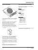
SAFETY Safety Decals Safety Decal on Leveler Frame Safety Decal on Platform Cylinder 4111-0004 — November 2003 OCT 2007 5
INTRODUCTION General Information Dock Leveler Stock Specifications EH dock levelers are available in the following sizes, weight capacities, and options: Width: EH 6 ft (1828.8 mm) 6-1/2 ft (1981.2 mm) 7 ft (2133.6 mm) Length 6 ft (1828.8 mm) 8 ft (2438 mm) 10 ft (3048 mm) 12 ft (3658 mm) Congratulations on your choice of a Poweramp dock leveler. This manual covers the EH series hydraulic dock leveler.
INTRODUCTION Component Identification L C A M G B F D N E K J H I A — Lip B — Lip Prop C —Platform D — Lip Cylinder H E — Powerpack (Motor/Pump/Reservoir) F — Platform Cylinder G— Main Frame H— Clean Sweep Removable Section H —Maintenance Prop Lock-Out J— Maintenance Prop K —Toe Guards (2 used) L —Control Box M —Raise Button N—ARTD Switch (option) THEORY The EH dock leveler uses hydraulic logic and one-button operation for ease of use.
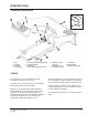
INSTALLATION Prepare Pit A C B D A—Distance (Pit Width) (Front and Rear) B— Distance (Dock Floor-to-Pit Floor) (All Four Corners) C— Distance (Pit Length) (Both Sides of Pit) D— Distance (Pit Corner-to-Corner) (Top, Bottom, and Both Sides) Before lowering the dock leveler into the pit, the following must be performed: Post safety warnings and barricade the work area at dock level and ground level to prevent unauthorized use of the dock leveler before installation has been completed.
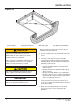
INSTALLATION Prepare Dock Leveler IMPORTANT DO NOT remove the shipping bands (B) around the platform lip and leveler frame at this time. The shipping bands are needed to hold the leveler together during the installation process. A 1. Remove any control panel and bumpers that may be banded to the frame of the dock leveler. DO NOT remove the shipping bands (B) around the platform lip and leveler frame at this time. IMPORTANT B A— Lifting Bracket (2 used) DO NOT overtighten the lifting bracket hardware.
INSTALLATION Install Dock Leveler Shim Stacking Methods N A P A Q R C B D A— Distance (Leveler Frame Height) B— Shim Locations (Under Rear Vertical Supports) C— Shim Location (Under Maintenance Prop) *Same as (D) D— Shim Locations (Under Lip Keepers) E— Dock Floor F— Rear Pit Curb Angle 10 G— String H— Rear Hinge Frame Angle J— Distance (Dock Floor-to-Pit Floor) K— Distance (Top of Shim Stack-to-Dock Floor) L— Shim Stack M— Dock Leveler Frame N — Pyramid (Preferred) P— Stepped (Acceptable) Q— Offset
INSTALLATION NOTE: Poweramp dock levelers are designed with a nominal 1/2 in. (12.7 mm) shimming distance to allow for pit inconsistencies. 4. For all EH models, put a 1/4 in. (6.6 mm) thick shim at locations (C and D) . 1. Determine height of shim stack (L) for each shim location (B) by performing the following: NOTE: A 1/4 in. (6.6 mm) thick shim at locations (C and D) is used only as a starting point. The final shim stack height will be determined after dock leveler is lowered into the pit. a.
INSTALLATION A B C C D D E F G A— Front of Dock Pit B— Dock Leveler Frame 3/8 in. (9.5 mm) 6 in. (152 mm) C— Side Pit Curb Angle D— Gap [3/4 in. (19 mm) Minimum] 8. With rear hinge frame angle (F) tight against rear pit curb angle (G), perform/check the following: • Pry between the platform and rear hinge frame angle at locations (E) to make sure rear edge of platform is parallel to the rear hinge frame angle (F).
INSTALLATION IMPORTANT DO NOT grind or weld if hydraulic fluid or other flammable liquid is present on the surface to be ground or welded. DO NOT grind or weld if uncontained hydraulic fluid or other flammable liquid is present. Stray sparks can ignite spills or leaks near the work area. Always clean up the oil leaks and spills before proceeding with grinding or welding. Always keep a fire extinguisher of the proper type nearby when grinding or welding.
INSTALLATION A E B C A— Platform Joists B— Shim Locations (Under Platform Cylinder Trunnions) C— Removable “Clean Sweep” Frame Section 14. Using an external lifting device (i.e., crane or fork truck) attached to the platform lifting brackets, slowly raise the platform. Check for binding as platform is being raised. 15. If binding occurs, lower the platform. Reposition leveler and/or add or remove shims as necessary. Slowly raise platform again.
INSTALLATION Make sure the platform is properly supported in the raised position before entering the pit to finish weld the shims. Failure to do this may result in serious personal injury or death. 18. All model levelers: Install shims at locations (B) using the pyramid or stepped shimming method. Both platform cylinder trunnions must be solidly shimmed the entire length of the trunnion. Make sure the trunnions are level from side-to-side as well as from front-to-back. 19.
INSTALLATION Install Control Panel and Wiring A The electrical power must be OFF prior to electrical installation. For maximum protection, use an OSHA approved locking device to lock out all power sources. Only the person installing the equipment should have the key to unlock the power source. Failure to follow these instructions may result in serious personal injury or death. B C DO NOT make any final electrical connections until all welding has been completed.
INSTALLATION Put New Dock Leveler Into Service 1. Disconnect the external lifting device and chains from the lifting brackets. 2. Check that the leveler is flush with the dock floor and that the platform lip contacts both lip keepers evenly. If an excessive transition exists between the dock floor and leveler and/or lip does not contact both lip keepers evenly, contact Poweramp Technical Services for further instructions. 3. Install the dock bumpers as required. 4. Turn the main electrical power ON.
OPERATION Operating Instructions Stay clear of dock leveler when freight carrier is entering or leaving dock area. 12 in. (305 mm) DO NOT move or use the dock leveler if anyone is under or in front of leveler. 12 in. (305 mm) Keep hands and feet clear of pinch points. Avoid putting any part of your body near moving parts. Failure to follow these instructions may result in severe personal injury or death. Only trained personnel should operate the dock leveler.
OPERATION Operating Instructions—Continued Ramp Loading/Unloading Instructions NOTE: If end unloading is required, see End Loading/Unloading Instructions on page 24. For ramp loading or unloading, the EH dock leveler can be operated by using the RAISE button on the control panel. 1. Check to make sure truck/trailer is positioned squarely against dock bumpers. 2. Instruct driver to remain at the dock until the loading or unloading process has been completed. 3.
OPERATION Operating Instructions—Continued End Loading/Unloading Instructions NOTE: If ramp loading is required, see Ramp Loading/Unloading Instructions on page 19. End loading or unloading can be done with the dock at the cross-traffic position or below-dock position, depending on the height of the truck/trailer bed. A A—ARTD Switch 1. Check to make sure truck/trailer is positioned squarely against dock bumpers. 2.
MAINTENANCE Service Dock Leveler Safely Side View F E A D B C G A— Tag-Out Device B — Lockout Device C — Lockout Device D — Tag-Out Device When service under the dock leveler is required, always lock all electrical disconnects in the OFF position after raising the platform and engaging the maintenance prop. Failure to do this may result in serious personal injury or death. Always stand clear of the dock leveler lip when working in front of the dock leveler.
MAINTENANCE Periodic Maintenance A F C E B D A— Lip Hinge Area B— Lip Lifter and Lip Cylinder Pin C— Platform Hinge Area D— Platform Cylinder Trunnion Before performing any maintenance under the dock leveler, lock the electrical power source in OFF position and lock the maintenance prop in the service position using an approved locking device. (See Service Dock Leveler Safely in this section.) Failure to follow these instructions may result in serious personal injury or death.
MAINTENANCE N P Q Regular maintenance must be performed on a weekly and quarterly schedule. Weekly Maintenance • Operate the dock leveler through the complete operating cycle to maintain lubrication. NOTE: To thoroughly inspect the platform hinge area, put the platform in the full below-dock position. • Inspect the platform hinge and the lip hinge areas. The hinge areas must be kept free of dirt and debris. Build-up of foreign material in the hinge areas will cause abnormal operation.
ADJUSTMENTS Valve Adjustment Procedure When service under the dock leveler is required, always lock all electrical disconnects in the OFF position after raising the platform and engaging the maintenance prop. Failure to do this may result in serious personal injury or death. Always post safety warnings and barricade the work area at dock level and ground level to prevent unauthorized use of the dock leveler before maintenance is complete. Failure to do this may result in serious personal injury or death.
ADJUSTMENTS Valve Adjustment Procedure E G F C D A B H A—S2 Valve B— RV1 Valve C—S1 Valve D— 2W NO Spool Valve/Coil E— NV1 Valve F— Breather Tube/Fitting G—To Hoist Cylinder H—To Lip Cylinder *Note: Not pictured on the bottom of the valve body are the RV2 and PO Check Valves S1 Sequence Valve 1 Controls the the Platform Cylinder. When the leveler has reached the top of its travel allow the leveler to float down. Fluid should flow through the NV1 valve.
This page intentionally left blank 26 4111-0004 — November 2003 OCT.
ADJUSTMENTS Adjust Auto Return To Dock (ARTD) Adjust the ARTD as Follows: E F D C When service under the dock leveler is required, always lock all electrical disconnects in the OFF position after raising the platform and engaging the maintenance prop. Failure to do this may result in serious personal injury or death.
ADJUSTMENTS IMPORTANT 6. Turn ON electrical power to the dock leveler. Anytime proximity switch and target are adjusted, always check for interference between target and switch before operating the leveler. Damage to switch will occur if the target contacts the switch. 7. Disengage the maintenance prop. The maximum torque for proximity switch lock nuts is 27 N•m (29 lb-ft). Damage to switch will occur if maximum torque is exceeded. 9.
ADJUSTMENTS Full Below-Dock Position Lip Fully Extended Position Lip Keeper Whenever the platform lip is at the fully extended position, the following conditions will exist for a normally operating ARTD: • Target not in the sensing area of proximity switch. Whenever the platform lip is at the full below-dock position, the following conditions will exist for a normally operating ARTD: • Proximity switch OFF (open) (no signal sent to the control panel). • Proximity switch indicator light is OFF.
This page intentionally left blank 30 4111-0004 — November 2003 OCT.
TROUBLESHOOTING Troubleshooting When service under the dock leveler is required, always lock all electrical disconnects in the OFF position after raising the platform and engaging the maintenance prop. Failure to do this may result in serious personal injury or death. Always post safety warnings and barricade the work area at dock level and ground level to prevent unauthorized use of the dock leveler before maintenance is complete. Failure to do this may result in serious personal injury or death.
TROUBLESHOOTING Symptom Three-phase units only: Platform does not rise. Motor hums, but does not run. Possible Cause Solution No voltage is present on one line. Check for blown fuses at branch circuit disconnect. Replace fuse. Determine cause of blown fuse. NOTE: A motor that is missing voltage on one line is said to be single-phased. Check motor starter as follows: 1. Disconnect wires at load side of starter. 2. Energize the starter. 3. Measure line-to-line voltage at line side of starter. 4.
TROUBLESHOOTING Symptom Platform does not rise. Pump operates in pressure relief mode. Possible Cause Solution Heavy object(s) on platform. Remove object(s) from platform. NOTE: For safety reasons, the dock leveler is designed to lift only the platform’s own weight. Dock leveler binds. Check for visible obstructions that could cause binding. Remove obstructions. If no obstructions found, call Poweramp Technical Services. See inside back cover for phone number and address. Pressure relief set too low.
TROUBLESHOOTING Symptom Possible Cause Platform does not rise to Low hydraulic fluid. full height. Solution Add fluid as needed. See Periodic Maintenance in the Maintenance section. Lip does not stay extended S1 Sequence Valve requires See Valve Adjustment Procedure Section adjustment 1/8” increments clockwise at a time Platform DOES rise to full height, but lip DOES NOT extend or extend fully. Low hydraulic fluid. Add fluid as needed. See Periodic Maintenance in the Maintenance section.
PARTS Controls B A C Item Quantity Part Number A B 1 1 C 1 0961-0085 * 9511-0004 9512-0429 Description Proximity Switch with Harness (ARTD Feature Only) Push Button Controller J-Box, Standard (4 x 4 in. Metal Box) J-Box, Cold Weather (5 x 5 in. Plastic Box) * Provide dock leveler serial number, voltage, phase, and options when calling or faxing controller orders.
PARTS Frame and Platform A T B S M R K P N Q L D C J E F G H U 36 4111-0004 — November 2003 OCT.
PARTS Frame and Platform Item Quantity Part Number A B C D E F G H J K L M N-P Q R S T U 1 1 1 1 1 6 3 1 1 1 1 AR AR AR 1 1 2 1 0595-____1 7823-____2 9515-____1 9202-____1 0015-____1 2101-0047 9202-0002 2101-0039 9222-0382 2101-0163 2101-0012 2101-0039 2101-0163 2101-0011 0015-____1 1751-0010 2101-0046 9225-____1 Description Lip, Welded Assembly Platform, Welded Assembly Pin, Lip Hinge Toe Guard Welded Assembly, Left Frame, EH Cotter Pin, 1/4 x 2 in.
PARTS Hydraulic Components H P E J O F G D C K L M N P L Q B R S TAE AA AB U V W A AC AD X Y 38 4111-0004 — November 2003 OCT.
PARTS Hydraulic Components Item Quantity A 1 B C D E F G H J K L M N O P Q R S T U V W X Y AA AB AC AD 1 1 1 1 1 1 2 1 2 1 1 1 1 1 1 1 1 1 1 4 4 4 4 1 1 1 1 Part Number 9391-0017 9391-0018 0521-0159 0525-0085 0522-0156 0521-0005 0522-0005 2101-0045 2101-0049 9202-0004 2101-0047 9202-0058 R509-0060 0521-0007 9301-0111 9904-____1 8581-0127 9904-____1 0521-0007 2101-0047 9202-0059 2101-0011 2101-0058 2101-0058 2101-0039 0000-0000 0000-0000 0000-0000 0000-0000 Description PPAC, Hoke H8, 1.
PARTS Power Pack Assembly A B D E C G F H J K L M AD N P O V AC AB AA U 40 Y X T S Q W Z R 4111-0004 — November 2003 OCT.
PARTS Power Pack Components Item Quantity A 1 B C D E F G H J K L M N O P Q R S T U 1 1 1 1 1 1 1 1 2 1 1 1 1 1 1 4 1 1 1 1 1 1 2 2 1 1 1 1 1 V W X Y Z AA AB AC AD 1 2 Part Number 3411-0047 3411-0048 8581-0134 8581-0133 0000-0000 8581-0130 0000-0000 8581-0128 8581-0129 8581-0128 2101-0227 9391-0028 0521-0007 0521-0161 9391-0032 9391-0031 9391-0030 2101-0225 2101-0226 2101-0110 9301-0209 9301-0207 9301-0208 9391-0029 9301-0105 * 0000-0000 9301-0105 8581-0132 8581-0131 9391-0027 Description Motor, Ho
PARTS Weather Seal, Rubber Style A Item Quantity Part Number A 3 0192-____* Description Foam Seal, Rear Hinge NOTE: Kits are for existing dock leveler without weather seal. * Provide dock leveler serial number and size of platform when calling or faxing orders. *Provide width of weatherstrip when replacing existing seals 42 4111-0004 — November 2003 OCT.
PARTS Weather Seal, Brush Style C A B Item A B C Quantity Part Number 1 1 1 1 1 1 1 1 1 0195-0018 0195-0021 0195-0024 0195-0027 0195-0030 0195-0033 0195-0036 0195-0039 0195-0044 Description 6’ Brush Seal and Track, 1 in. (25 mm) 8’ Brush Seal and Track, 1 in. (25 mm) 10’ Brush Seal and Track, 1 in. (25 mm) 12’ Brush Seal and Track, 1 in.
NOTES 44 4111-0004 — November 2003 OCT.
MISCELLANEOUS Customer Information A NOTE: Refer to illustration for left/right orientation of dock leveler. The model/serial number decal (A) is located on the right platform joist near the front (lip) of dock leveler. When you receive your EH dock leveler, write down the dock leveler model and serial number in the form provided. This will help ensure safe keeping of the numbers in the event the model/serial number decal (A) becomes lost or damaged. Also, write down Systems, Inc.
POWERAMP WARRANTY EH SERIES LEVELER Systems, Inc., guarantees the materials, components, and workmanship in your Poweramp dock leveler to be of the highest quality and to be free of defects in material and workmanship with the Structure, Hydraulic and Electrical for One (1) year. Systems, Inc., further guarantees the hydraulic components on all Poweramp dock levelers for an additional Two (2) years, or Three (3) years total from date of shipment.