CM-Series Dock Leveler Owner’s/User’s Manual Poweramp • Division of Systems, Inc. • W194 N11481 McCormick Drive • Germantown, WI 53022 800.643.5424 • fax: 262.255.5917 • www.docksystemsinc.com • techservices@docksystemsinc.com Printed in U.S.A. Copyright © 2003 Manual No.
Table of Contents Page Safety Recognize Safety Information.............................................................. General Operational Safety Precautions............................................. Operational Safety Precautions............................................................ Maintenance Safety Precautions.......................................................... Safety Decals..........................................................................................
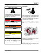
SAFETY Recognize Safety Information General Operational Safety Precautions Safety-Alert Symbol The Safety-Alert Symbol identifies important safety messages on equipment, safety signs, in manuals, or elsewhere. When you see this symbol, be alert to the possibility of personal injury or death. Follow the instructions in the safety message. Read and understand the operating instructions and become thoroughly familiar with the equipment and its controls before operating the dock leveler.
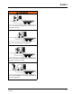
SAFETY Operational Safety Precautions Learn the safe way to operate this equipment. Read and understand the manufacturer’s instructions. If you have any questions, ask your supervisor. Stay clear of dock leveling device when freight carrier is entering or leaving area. Chock/restrain all freight carriers. Never remove the wheel chocks until loading or unloading is finished and truck driver has been given permission to drive away.
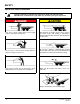
SAFETY Do not use dock leveling device if freight carrier is too high or too low. Do not overload the dock leveling device. Do not operate any equipment while under the influence of alcohol or drugs. Do not leave equipment or material unattended on dock leveling device.
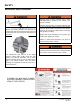
SAFETY Maintenance Safety Precautions DO NOT grind or weld if hydraulic fluid or other flammable liquid is present on the surface to be ground or welded Always post safety warnings and barricade the work area at dock level and ground level to prevent unauthorized use of the unit before maintenance is complete. DO NOT grind or weld if uncontained hydraulic fluid or other flammable liquid is present. Stray sparks can ignite spills or leaks near the work area.
SAFETY Safety Decals 5.06" DANGER 1751-0727 CRUSH HAZARD Maintenance prop must support leveler behind bar. Do not force maintenance prop forward of bar to support lip. Failure to comply will result in death or serious injury. Refer to owner’s/user’s manual for proper use. 2.40" Every 90 days (quarterly) inspect all safety labels and tags to ensure they are on the dock leveler and are easily legible. If any are missing or require replacement, please call 1-800-643-5424 for replacements.
OWNER’S/USER’S RESPONSIBILITIES 1. The owner/ user should recognize the inherent dangers of the interface between the loading dock and the transportation vehicle. The owner/ user should, therefore, train and instruct all operators in the safe operation and use of the loading dock equipment in accordance with manufacturer’s recommendations and industry standards. Effective operator training should also focus on the owner’s/user’s company policies and operating conditions.
INTRODUCTION General Information Dock Leveler Stock Specifications CM-Series dock levelers are available in the following sizes, weight capacities, and options: Width 6 ft (1828.8 mm) 6-1/2 ft (1981.2 mm) 7 ft (2133.6 mm) Length 5 ft 6 ft 8 ft 10 ft Congratulations on your choice of a Poweramp dock leveler. This manual covers the CM-series mechanical dock leveler.
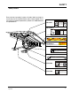
INTRODUCTION Component Identification D C E B F S U T A Q P R N M G H K J L A — Lip B — Lip Maintenance Prop C — Platform D — Lip Banger E — Lip Assist Spring 8 F — Platform Release Ring G — Ratchet Pawl H — Ratchet Bar J — Release Arm Spring K — Main Frame L — Platform Maintenance Prop M— Hold-Down Mechanism N — Safety Leg (2 used) P — Lip (Snubber) Spring Q — Lip Shock Absorber R— Safety Leg Linkage S — Safety Leg Release Ring T — Lift Arm Assembly U — Lift (Main) Spring Assembly 411
INSTALLATION Prepare Pit A C B D A— Distance (Pit Width) (Front and Rear) B — Distance (Dock Floor-to-Pit Floor) (All Four Corners) C — Distance (Pit Length) (Both Sides of Pit) D — Distance (Pit Corner-to-Corner) (Top, Bottom, and Both Sides) 1. Before lowering the dock leveler into the pit, the following must be performed: Post safety warnings and barricade the work area at dock level and ground level to prevent unauthorized use of the dock leveler before installation has been completed.
INSTALLATION Prepare Dock Leveler A B A— Lifting Bracket (2 used) The dock leveler is heavy. Use a lifting device and chains with the appropriate lifting capacity and reach. Always use the lifting brackets provided with the unit whenever lowering or lifting a dock leveler into or out of a pit. B — Shipping Bands Poweramp dock levelers are designed with installation in mind. Each unit is shipped with lifting brackets (A) fastened to the platform side joists.
INSTALLATION 1. Remove any bumpers that may be banded, or bolted to the frame of the dock leveler. DO NOT remove the shipping bands (B) around the platform lip and leveler frame at this time. IMPORTANT DO NOT over-tighten the lifting bracket hardware. Over-tightening can damage the weather seal, if equipped. NOTE: Overall width of platform and lifting brackets (A) must be kept to a minimum to prevent interference between the lifting brackets and the pit walls as the dock leveler is lowered into the pit. 2.
INSTALLATION Install Dock Leveler Shim Stacking Methods M PLACARD N A P Q B C D A— Distance (Leveler Frame Height) B— Shim Locations (Under Rear Vertical Supports) C— Shim Locations (Under Lip Keepers and Prop) D— Dock Floor E— Rear Pit Curb Angle F— String G— Rear Hinge Frame Angle 12 H— Distance (Dock Floor-to-Pit Floor) J— Distance (Top of Shim Stack-to-Dock Floor) K— Shim Stack L— Dock Leveler Frame M — Pyramid (Preferred) N— Stepped (Acceptable) P— Offset (Not Acceptable) Q — Straight (Not Ac
INSTALLATION NOTE: Poweramp dock levelers are designed with a nominal 1/2 in. (12.7 mm) shimming distance to allow for pit inconsistencies. 1. Determine height of shim stack (K) for each shim location (B) by performing the following: a. Measure leveler frame height distance (A). b. Measure dock floor-to-pit floor distance (H) at each shim location (B). Write down the dimensions obtained at each location. c. Subtract distance (A) from distance (H) to obtain the shim height. Repeat for each shim location.
INSTALLATION A B B C C D D E F G A— Front of Dock Pit B— Dock Leveler Frame 3/8 in. (9.5 mm) H 6 in. (152 mm) C— Side Pit Curb Angle D— Gap [3/4 in. (19 mm) Minimum] E— Pry Locations F— Rear Hinge Frame Angle 8. With rear hinge frame angle (F) tight against rear pit curb angle (G), perform/check the following: • Pry between the platform and rear hinge frame angle at locations (E) to make sure rear edge of platform is parallel to the rear hinge frame angle (F).
INSTALLATION DO NOT grind or weld if hydraulic fluid or other flammable liquid is present on the surface to be ground or welded. DO NOT grind or weld if uncontained hydraulic fluid or other flammable liquid is present. Stray sparks can ignite spills or leaks near the work area. Always clean up the oil leaks and spills before proceeding with grinding or welding. Always keep a fire extinguisher of the proper type nearby when grinding or welding.
INSTALLATION A C B D A— Locking A—Safety Safety Leg Leg Chain Chain Pull Pull Ring Ring B— B—Platform Platform Maintenance Maintenance Prop Prop CC— —Shim Shim Location Location (Under (Under Lift Lift Arm Arm Pivot) Pivot) DD— —Prop PinDevice & Clip 21. Pull the release ring to raise platform. Engage the platform maintenance prop (B) in the service (upright) position and lock the maintenance prop at this position using an OSHA approved locking device (D). Engage lip maintenance prop.
OPERATION B D C E F S T U A Q R P N M H G J K L A — Lip B — Lip Maintenance Prop C — Platform D — Lip Banger E — Lip Assist Spring F — Platform Release Ring G— Ratchet Pawl H — Ratchet Bar J — Release Arm Spring K — Main Frame The CM-series mechanical dock leveler uses large lift springs (U) to apply force to lift arm (T). The lift arm pushes against the underside of the platform (C), rolling on the cam (not pictured) forcing the platform to rise.
OPERATION Operating Instructions Stay clear of dock leveler when freight carrier is entering or leaving dock area. 12 in. (305 mm) DO NOT raise or lower the dock leveler if anyone is under or in front of leveler. Keep hands and feet clear of pinch points. Avoid putting any part of your body near moving parts. Failure to follow these instructions may result in severe personal injury or death.
OPERATION Operating Instructions — Continued Ramp Loading/Unloading Instructions NOTE: If end unloading is required, see End Loading/ Unloading Instructions on page 20. 1. Check to make sure truck/trailer is positioned squarely against dock bumpers. 7. Make sure that the lip is fully extended and supported on the truck/trailer along the entire width of the platform with at least 4 in. (102 mm) of lip contacting the truck bed. 2.
OPERATION Operating Instructions — Continued End Loading/Unloading Instructions NOTE: End loading or unloading can be done with the dock at the cross-traffic position or below‑dock position depending on the height of the truck/ trailer bed. B 1. Check to make sure truck/trailer is positioned squarely against dock bumpers. 2. Instruct driver to remain at the dock until the loading or unloading process has been completed. 3. Chock the truck/trailer wheels or use truck restraint if present.
MAINTENANCE Service Dock Leveler Safely A B D C A— Lip Maintenance Prop B — Platform Maintenance Prop Always post safety warnings and barricade the work area at dock level and ground level to prevent unauthorized use of the dock leveler before maintenance is complete. Failure to do this may result in serious personal injury or death. Always stand clear of the dock leveler lip when working in front of the dock leveler. Failure to do this may result in serious personal injury or death.
MAINTENANCE Periodic Maintenance A D C B • E L K F J G H A — Lip Hinge Grease Fittings B — Lip Maintenance Prop Pivot C — Lip Banger Pivots D — Platform Hinge Area E — Lift Arm Roller Bushing F — E-Z Release Bellcrank Pivot G — Lift Arm Pivot H — Hold-Down Pivot/Pulley Always post safety warnings and barricade the work area at dock level and ground level to prevent unauthorized use of the dock leveler before maintenance is complete.
MAINTENANCE Regular maintenance must be performed on a weekly and quarterly schedule. Weekly Maintenance Quarterly Maintenance • O perate the dock leveler through the complete operating cycle to maintain lubrication. • L ubricate the following areas with light-weight machine oil: NOTE: To thoroughly inspect the platform hinge area, position the platform in the full below‑dock position. (B)— Lip maintenance prop pivot • I nspect the platform hinge and the lip hinge areas.
ADJUSTMENTS Adjust Lift Arm Spring and Lip Assist Spring Tension A B D C E F A — Jam Nut B —Adjustment Nut C — Lip Assist Spring D — Lift Springs Always post safety warnings and barricade the work area at dock level and ground level to prevent unauthorized use of the dock leveler before maintenance is complete. Failure to do this may result in serious personal injury or death. Always stand clear of the dock leveler lip when working in front of the dock leveler.
ADJUSTMENTS NOTE: Adjusting the tension of lift springs (D) usually requires that the lip assist spring (C) also be adjusted. If the platform does not rise fully and/or lip does not extend fully, the lift spring tension may be set too low. If the platform cannot be walked down or is difficult to walk down, the lift spring tension may be set too high. 3. After lift spring adjustment is completed, check operation of the lip.
ADJUSTMENTS Adjust Lip Stop Bolt Always post safety warnings and barricade the work area at dock level and ground level to prevent unauthorized use of the dock leveler before maintenance is complete. Failure to do this may result in serious personal injury or death. A B Always stand clear of the dock leveler lip when working in front of the dock leveler. Failure to do this may result in serious personal injury or death.
ADJUSTMENTS This page intentionally left blank 4111-0006 — Sept 2010 Sept 2012 27
TROUBLESHOOTING Troubleshooting Always post safety warnings and barricade the work area at dock level and ground level to prevent unauthorized use of the dock leveler before maintenance is complete. Failure to do this may result in serious personal injury or death. Always stand clear of the dock leveler lip when working in front of the dock leveler. Failure to do this may result in serious personal injury or death. Symptom Platform does not rise.
TROUBLESHOOTING Symptom Platform rises to full height, but lip does not fully extend. Possible Cause Lip assist chain disconnected or broken. Connect or replace chain. Insufficient main spring tension. Increase tension on main lift springs. (See Adjust Lift Arm Spring and Lip Assist Spring Tension in the Adjustments section.) Insufficient lip assist force. Increase lip assist spring tension. (See Adjust Lift Arm Spring and Lip Assist Spring Tension in the Adjustments section.
TROUBLESHOOTING This page intentionally left blank 30 4111-0006 — Sept 2010 Sept 2012
PARTS Hold-Down Mechanism B D C Item Quantity 1 B 1 C D 1 1 4111-0006 — Sept 2010 Sept 2012 Part Number DOTH-2563 DOTH-2564 DKIT-2575 DKIT-2576 1751-0043 DOTH-2559 Description Hold Down Assembly Complete, 31.5” Ratchet Bar Hold Down Assembly Complete, 34.5” Ratchet Bar Ratchet Bar and Pawl Assembly 31.5” Ratchet Bar Ratchet Bar and Pawl Assembly 34.
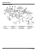
PARTS Frame Components F J K L G F M AD F L E AB D N AE AD C P L Q P B P S AA A Z V Y U P T W X BASE FRAMES ITEM QTY A 1 32 6’ LONG 8’ LONG 10’ LONG 6’ WIDE 20K/50K 6’ WIDE 20K/50K 6’ WIDE 20K/50K 16 DRFA-1003 16 DRFA-1012 16 DRFA-1021 18 DRFA-1004 18 DRFA-1013 18 DRFA-1022 20 DRFA-1005 20 DRFA-1014 20 DRFA-1023 6.5’ WIDE 20K/50K 6.5’ WIDE 20K/50K 6.
PARTS Frame Components Item Quantity Part Number A 1 B C D E W 1 1 1 1 1 1 1 1 1 1 AR* 5 3 1 4 1 1 1 1 1 1 1 1 1 X 2 Y Z AA 1 1 1 1 1 1 1 F G J K L M N P Q S T U V AB AD AE DFRA____ DFRA-____ 1 DOTH-2555 DOTH-2416 DPLA-2128 DOTH-2421 DFRA-0326 DFRA-0327 DOTH-2222 DOTP-6424 1 DOTP-6423 1 DOTH-2402 DOTH-____ 1 DOTH-2382 9202-0002 DOTH-2061 DOTH-2432 DOTH-2423 DOTH-2131 DLPA-1210 DOTH-6929 DPLA-1211 1 DPLA-12111 DPLA-12111 DOTP-6924 1 DOTP-____ 1 8432-0983 1 8432-0984 1 8432-0985 1 8432-0986 1 8432-
PARTS Platform Components U M V X L X R N Q P S J G T D C E K H F AE C AB AC AN A AH AA AM AG Y AJ Z AK AL AE AD AQ AP AF AO 34 4111-0006 — Sept 2010 Sept 2012
PARTS Platform Components Item Quantity A C D E F G H J K L 1 AR* 1 2 1 2 1 1 1 1 2 2 2 See Page 34 DOTH-2424 DOTH-2075 DOTH-2160 DOTH-2131 DOTH-2214 DOTH-2547 DOTP-2006 DOTH-2062 See Page 34 DPLA-2101 DLPA-2102 DLPA-2103 Platform, Welded Assembly Fitting, Grease Cap Screw, Lip Stop Nut, Hex 5/8-11 Nut, Nylon Lock Washer Spring, Lip Maintenance Prop Prop, Lip Maintenance Cap Screw Lip, Welded Assembly Pin, Lip Hinge 6 ft wide Pin, Lip Hinge 6.
PARTS Platform Components Continued from previous page 6’ Long ITEM QTY A PLATFORMS 8’ Long 6.0’ Wide 6.5’ Wide 7.0’ Wide 6.0’ Wide 6.5’ Wide 10’ Long 7.0 FOOT 6.0’ Wide 6.5’ Wide 7.0’ Wide 1 25K DPLA-1008 DPLA-1029 DPLA-1050 25K DPLA-1015 DPLA-1036 DPLA-1057 25K DPLA-1022 DPLA-1043 DPLA-1064 1 30K DPLA-1009 DPLA-1030 DPLA-1051 35K DPLA-1016 DPLA-1037 DPLA-1058 35K DPLA-1023 DPLA-1044 DPLA-1065 L LIPS QTY. 25K 30K 6.
PARTS Platform Components 55 56 57 58 SEE CHART DOTH-2570 SPRING MAIN 6620 SEE CHART DOTH-2574 SPRING MAIN 6635 SEE CHART DOTH-2576 SPRING MAIN 6820 SEE CHART DOTH-2578 SPRING MAIN 6835 A B C SEE CHART DOTH-2550 REG LIP SPRING (ORANGE) SEE CHART DOTH-2546 HEAVY DUTY LIP SPRING (GREEN) SEE CHART DOTH-2548 STANDARD LIP SPRING (WHITE) 6’ LONG 6.
PARTS Platform Components B C CC A D K E F E G H J 38 4111-0006 — Sept 2010 Sept 2012
PARTS Toe Guard/Weather Seal—Optional Item A B C CC Quantity 2 2 2 2 D-K 1 1 Part Number DOTH-2818 DOTH-2824 DOTH-2820 DOTH-2822 DKIT-9178 DKIT-9179 DKIT-9180 DKIT-9181 DKIT-9293 DKIT-9292 4111-0006 — Sept 2010 Sept 2012 Description Channel, Weather Seal, 84” T-Rubber, Weather Seal, 84” Extrusion, Brush Weather Seal, 84” Brush Weather Seal, 1.
NOTES This page intentionally left blank 40 4111-0006 — Sept 2010 Sept 2012
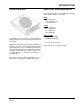
MISCELLANEOUS Customer Information A NOTE: Refer to illustration for left/right orientation of dock leveler. The model/serial number decal (A) is located on the right platform joist near the front (lip) of dock leveler. When you receive your CM-series dock leveler, write down the dock leveler model and serial number in the form provided. This will help ensure safe keeping of the numbers in the event the model/serial number decal (A) becomes lost or damaged.
STANDARD PRODUCT WARRANTY SYSTEMS, INC. warrants that its products will be free from defects in design, materials and workmanship for a period of one (1) year from the date of shipment. All claims for breach of this warranty must be made within 30 days after the defect is or can with reasonable care, be detected. In no event shall any claim be made more than 30 days after this warranty has expired.