CentraAir™ Dock Leveler Owner’s / User’s Manuals POWERAMP® • Division of Systems, Inc. • W194 N11481 McCormick Drive • Germantown, WI 53022 800.643.5424 • fax: 262.255-5917 • www.docksystemsinc.com • techservices@docksystemsinc.com Printed in U.S.A. Copyright © 2012 Manual No.
Table of Contents Safety Page Recognize Safety Information.............................................................. General Operational Safety Precautions............................................. Operational Safety Precautions............................................................ Maintenance Safety Precautions.......................................................... Safety Decal’s.........................................................................................
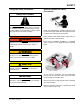
SAFETY Recognize Safety Information Safety-Alert Symbol The Safety-Alert Symbol identifies important safety messages on equipment, safety signs, in manuals, or elsewhere. When you see this symbol, be alert to the possibility of personal injury or death. Follow the instructions in the safety message. General Operational Safety Precautions Read and understand the operating instructions and become thoroughly familiar with the equipment and its controls before operating the dock leveler.
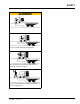
SAFETY SAFETY Operational Safety Precautions Learn the safe way to operate this equipment. Read and understand the manufacturer’s instructions. If you have any questions, ask your supervisor. Stay clear clear ofofdock dockleveling leveling device device when when freight freight carrier is entering or leaving area. Chock/restrain all all freight freightcarriers. carriers.
SAFETY Do not use dock leveling device if freight carrier is too high or too low. Do not overload the dock leveling device. Do not operate any equipment while under the influence of alcohol or drugs. Do not leave equipment or material unattended on dock leveling device. 4111-0023 — Jan.
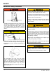
SAFETY Maintenance Safety Precautions ALWAYS disconnect electrical power source and ground wire before welding on dock leveler. DO NOT ground welding equipment to any hydraulic or electrical components of the dock leveler. Always ground to the dock leveler frame. Failure to follow these instructions may result in damage to dock leveler and/or serious personal injury or death. Hydraulic and electrical power must be OFF when servicing the equipment.
SAFETY Safety Decal’s Every 90 days (quarterly) inspect all safety labels and tags to ensure they are on the dock leveler and are easily legible. If any are missing or require replacement, please call 1-800-643-5424 for replacements. 5.06" DANGER 2.40" 1751-0727 CRUSH HAZARD Maintenance prop must support leveler behind bar. Do not force maintenance prop forward of bar to support lip. Refer to owner’s/user’s manual for proper use. Failure to comply will result in death or serious injury.
OWNER’S/USER’S RESPONSIBILITIES 1. The owner/user should recognize the inherent dangers of the interface between the loading dock and the transportation vehicle. The owner/user should, therefore, train and instruct all operators in the safe operation and use of the loading dock equipment in accordance with manufacturer’s recommendations and industry standards.
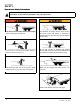
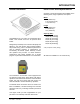
INTRODUCTION General Information Dock Leveler Stock Specifications CentraAir™ Series dock levelers are available in the following sizes, weight capacities, and options: Width: 6 ft (1828.8 mm) 6-1/2 ft (1981.2 mm) 7 ft (2133.6 mm) Length 6 ft (1828.8 mm) 8 ft (2438 mm) 10 ft (3048 mm) Congratulations on your choice of a Poweramp® dock leveler. This manual covers the air powered dock leveler.
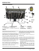
INTRODUCTION Component Identification A E O N C R B M Q D L G P F K A — Lip B — Lip Assist Rod C —Lip Linkage Assembly D — Lip Latch Assembly J E — Lip Maintenance Prop Pivot) F — Lip Actuator Chain Spring G — Lip Actuator Chain H — Lip Actuator Chain Adjustment Link I I — Lip Keepers (2 used) J — Air Bellows K — Main Frame L — Maintenance Prop M —Toe Guard (2 used) N —Raise Button O —Safety Legs P —Air Control Valve Q —Lanyard R —Filter/Regulator THEORY The CA dock leveler uses Compressed Air
INSTALLATION Prepare Pit A C B D A—Distance (Pit Width) (Front and Rear) B— Distance (Dock Floor-to-Pit Floor) (All Four Corners) Post safety warnings and barricade the work area at dock level and ground level to prevent unauthorized use of the dock leveler before installation has been completed. Failure to follow the installation instructions can result in damage to dock leveler, the facilities, and/ or serious personal injury or death.
INSTALLATION Prepare Dock Leveler IMPORTANT A DO NOT remove the shipping bands (B) around the platform lip and leveler frame at this time. The shipping bands are needed to hold the leveler together during the installation process. 1. Remove any control panel and bumpers that may be banded to the frame of the dock leveler. DO NOT remove the shipping bands (B) around the platform lip and leveler frame at this time.
INSTALLATION Shim Stacking Methods Install Dock Leveler M N O P R Q D E C A— Distance (Leveler Frame Height) B— Shim Locations (Under Rear Vertical Supports) C— Shim Location (Under Lip Keepers) D— Shim Locations (Under Maintenance Prop) E— Shim Locations (Under Lip Spring) F— Dock Floor G— Rear Pit Curb Angle H— String I— Rear Hinge Frame Angle J— Distance (Dock Floor-toPit Floor) 4111-0023 — Jan.
INSTALLATION NOTE: Poweramp® dock levelers are designed with a nominal 1/2 in. (12.7 mm) shimming distance to allow for pit inconsistencies. 1. Determine height of shim stack (L) for each shim location (B) by performing the following: a. Measure leveler frame height distance (A). 4. For all CentraAir™ models, put a 1/4 in. (6.6 mm) thick shim at locations (C and D) . NOTE: A 1/4 in. (6.6 mm) thick shim at locations (C and D) is used only as a starting point.
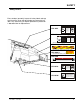
INSTALLATION B A C C D D E F G A— Front of Dock Pit B— Dock Leveler Frame 3/8 in. (9.5 mm) 6 in. (152 mm) C— Side Pit Curb Angle D— Gap [3/4 in. (19 mm) Minimum] 8. With rear hinge frame angle (F) tight against rear pit curb angle (G), perform/check the following: • Pry between the platform and rear hinge frame angle at locations (E) to make sure rear edge of platform is parallel to the rear hinge frame angle (F).
INSTALLATION 12. W ith the leveler square in the pit and flush with the surrounding dock, remove the banding on the lip of the leveler. 13. Lift Leveler with appropriate machinery. Two people are required to engage the maintenance prop: one person to operate the lifting device, the other person to engage the maintenance prop. 14. Slowly raise the platform. Check for binding as platform is being raised. 15. If binding occurs, lower the platform.
INSTALLATION IMPORTANT DO NOT grind or weld if hydraulic fluid or other flammable liquid is present on the surface to be ground or welded. DO NOT grind or weld if uncontained hydraulic fluid or other flammable liquid is present. Stray sparks can ignite spills or leaks near the work area. Always clean up the oil leaks and spills before proceeding with grinding or welding. Always keep a fire extinguisher of the proper type nearby when grinding or welding.
INSTALLATION Install Control Panel and Wiring A The electrical power must be OFF prior to electrical installation. For maximum protection, use an OSHA approved locking device to lock out all power sources. Only the person installing the equipment should have the key to unlock the power source. Failure to follow these instructions may result in serious personal injury or death. B C DO NOT make any final electrical connections until all welding has been completed.
INSTALLATION Put New Dock Leveler Into Service 1. Disconnect the external lifting device and chains from the lifting brackets. 2. Check that the leveler is flush with the dock floor and that the platform lip contacts both lip keepers evenly. If an excessive transition exists between the dock floor and leveler and/or lip does not contact both lip keepers evenly, contact Poweramp® Technical Services for further instructions. 7.
OPERATION Operating Instructions Stay clear of dock leveler when freight carrier is entering or leaving dock area. 12 in. (305 mm) DO NOT move or use the dock leveler if anyone is under or in front of leveler. 12 in. (305 mm) Keep hands and feet clear of pinch points. Avoid putting any part of your body near moving parts. Failure to follow these instructions may result in severe personal injury or death. Only trained personnel should operate the dock leveler.
OPERATION Operating Instructions—Continued Below Dock Loading/Unloading Instructions Ramp Loading/Unloading Instructions NOTE: If end unloading is required, see End Loading/Unloading Instructions on page 20. NOTE: If end unloading is required, see End Loading/Unloading Instructions on page 20. 7. Check to make sure truck/trailer is positioned squarely against dock bumpers.
OPERATION Operating Instructions—Continued End Loading/Unloading Instructions NOTE: If ramp loading is required, see Ramp Loading/Unloading Instructions on page 19. End loading or unloading can be done with the dock at the cross-traffic position or below-dock position, depending on the height of the truck/ trailer bed. 1. Check to make sure truck/trailer is positioned squarely against dock bumpers. 2. Instruct driver to remain at the dock until the loading or unloading process has been completed. 3.
MAINTENANCE Service Dock Leveler Safely A D C B A— Maintenance Prop B —Tag Out Device When service under the dock leveler is required, always lock all electrical disconnects in the OFF position after raising the platform and engaging the maintenance prop. Failure to do this may result in serious personal injury or death. Always stand clear of the dock leveler lip when working in front of the dock leveler. The maintenance prop MUST be in the service position when working under the dock leveler.
MAINTENANCE Periodic Maintenance A B C E D G A— Lip Hinge Area B— Lip Maintenance Prop Pivot Recommend 95 Psi C— Lip Link Pivots D— Platform Hinge Area E— Lip Assist Pin G— Safety leg linkage pivots Adjusting knob Clockwise increase PSI Counter Clockwise decrease PSi Inlet Supply line to dock leveler Fill line with Kill Frost or equivalent (lubricator may not be on ever unit) Clean Filter as needed Drain water as needed 22 4111-0023 — Jan.
MAINTENANCE Regular maintenance must be performed on a weekly and quarterly schedule. Weekly Maintenance • Operate the dock leveler through the complete operating cycle to maintain lubrication. NOTE: To thoroughly inspect the platform hinge area, put the platform in the full below-dock position. • Inspect the platform hinge and the lip hinge areas. The hinge areas must be kept free of dirt and debris. Build-up of foreign material in the hinge areas will cause abnormal operation.
ADJUSTMENTS Adjusting the Latch and Lip Actuator Spring Tension When service under the dock leveler is required, always lock all electrical disconnects in the OFF position after raising the platform and engaging the maintenance prop. Failure to do this may result in serious personal injury or death. B Always post safety warnings and barricade the work area at dock level and ground level to prevent unauthorized use of the dock leveler before maintenance is complete.
ADJUSTMENTS Adjusting Lip Latch Spring Tension Adjusting Lip Actuator Spring Tension This adjustment is set at the factory and should not require additional adjustment. This adjustment is set at the factory and should not require additional adjustment. Unlike mechanical levelers, the lip will not immediately begin to fold as the platform returns to the stored position. Unlike mechanical levelers, the lip will not immediately begin to fold as the platform returns to the stored position.
ADJUSTMENTS Adjust Lip Stop Bolt Always post safety warnings and barricade the work area at dock level and ground level to prevent unauthorized use of the dock leveler before maintenance is complete. Failure to do this may result in serious personal injury or death. A B Always stand clear of the dock leveler lip when working in front of the dock leveler. Failure to do this may result in serious personal injury or death.
NOTES This page intentionally left blank 4111-0023 — Jan.
TROUBLESHOOTING TROUBLESHOOTING Troubleshooting When service under the dock leveler is required, always lock all electrical disconnects in the OFF position after raising the platform and engaging the maintenance prop. Failure to do this may result in serious personal injury or death. Always post safety warnings and barricade the work area at dock level and ground level to prevent unauthorized use of the dock leveler before maintenance is complete.
TROUBLESHOOTING Symptom Possible Cause Low Air pressure Platform does not rase No voltage to solenoid Solution Minimum 80 Psi required at regulator, if lower check air supply.
Electrical Controls 30 4111-0023 — Jan.
Control Box 4” A B 6” 4” 0.5 FLA Amp Draw Item Quantity Part Number A 1 7141- B 1 1751-0801 4111-0023 — Jan.
PARTS H A D E G L C J F B I Item Quantity Part Number A B C D E F G H I J K L 1 1 1 2 2 A/R 1 1 1 1 A/R 1 7955-001 8103-0001 5402-0009 2101-0008 2101-0143 8581-0158 9512-0261 9301-0236 9301-0237 8581-0152 0521-0178 Description Cable Assembly (Includes Pull Ring) Weight Assembly Lanyard Arm Bolt ¼” x 2” Lg Lock Nut ¼” ⅜ Nylon Air Line Valve Operator, Mechanical---REF--Lanyard Control Bracket Fitting, Straight Fitting, Elbow Clamp, Air Line (Not Shown) Down Speed Control D A B C E G H Item Qua
PARTS Below Dock Control D G H I E F B A J Item Quantity Part Number A B C D E F 1 1 1 1 1 1 9514-0108 9514-0109 Leg, Right Safety Assembly with Spring.
PARTS Pit Extension Kit 1 Item Quantity Part Number 1 1 8436-0035 34 Description 4 inch Pit Extension Kit, For all size levelers 4111-0023 — Jan.
PARTS F E C D B A Item Quantity Part Number Description A 1 5811-0002 Air Bellows B 1 9514-0160 Top Mounting Weldment C 1 9512-2090 Pin, 49/64 X 10-¾ Lg. D 2 2101-0045 Cotter Pin E 8 2101- ⅜ x1” Lg.
PARTS Frame and Platform A N M B E F G C K H J L I O 36 4111-0023 — Jan.
PARTS Frame and Platform 1 2 Item Quantity A B 1 1 C 1 D Part Number Description 1 See Table A 9515-____2 9202-0050 9202-0051 9202-0052 DKIT-9179 Lip, Welded Assembly Platform, Welded Assembly Pin, Lip Hinge 6’W Pin, Lip Hinge 6.
PARTS Lip Activation Located on Deck Located on Lip R J S G M P Q H I E D G F T U O A S B K L M G C Item Quantity A B 1 1 C 1 D E F G H I J K L M N O P Q R S T U 1 1 2 2 1 1 1 1 1 5 1 1 1 1 1 1 2 2 38 Part Number 9513-00 2101-0221 9511-0156 9514-0114 9513-0097 2101-0051 2101-0004 2101-0103 2101-0222 2101-0223 9514-0091 5775-0004 2101-0220 2101-0079 2101-0045 0941-0006 DPLA-2128 DOTH-2416 DOTH-2421 DPLA-0341 DOTH-2061 DOTH-2131 Description Lip Assist Rod Complete 34” Lg (Includes Nuts)
PARTS Weather Seal C A B Item A B C Quantity Part Number 1 1 1 1 1 1 1 1 1 0195-0018 0195-0021 0195-0024 0195-0027 0195-0030 0195-0033 0195-0036 0195-0039 0195-0044 Description Brush Seal and Track, 1 in (25mm) Brush Seal and Track, 1 in. (25 mm) Brush Seal and Track, 1 in. (25 mm) Brush Seal and Track, 1 in. (25 mm) Rubber Seal and Track, 1 in. (25 mm) Rubber Seal and Track, 1 in. (25 mm) Rubber Seal and Track, 1 in. (25mm) Rubber Seal and Track, 1 in.
Notes 40 4111-0023 — Jan.
MISCELLANEOUS Customer Information A NOTE: Refer to illustration for left/right orientation of dock leveler. Dock Leveler Information The model/serial number decal (A) is located on the right platform joist near the front (lip) of dock leveler. Model ___________________________________ When you receive your AP-Series dock leveler, write down the dock leveler model and serial number in the form provided.
STANDARD PRODUCT WARRANTY SYSTEMS, INC. warrants that its products will be free from defects in design, materials and workmanship for a period of one (1) year from the date of shipment. All claims for breach of this warranty must be made within 30 days after the defect is or can with reasonable care, be detected. In no event shall any claim be made more than 30 days after this warranty has expired.