SPIRAL BEVEL GEARBOXES RANGE “N” SPARES LIST & MAINTENANCE INSTRUCTIONS Manual: MM-SBG(N)-E-02 SUPPLIED BY: POWER JACKS LIMITED 1
SPIRAL BEVEL GEARBOXES RANGE “N” CONTENTS 1. UNIT DETAILS ......................................................................................................................................................................... 2 2. POWER RATINGS .................................................................................................................................................................. 3 2.1 3. GENERAL INSTRUCTIONS ..................................................................
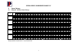
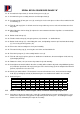
SPIRAL BEVEL GEARBOXES RANGE “N” 2. Power Ratings 2.1 Range N – Gearbox Power Ratings -1 Gear Unit Ratio 10 kW 50 Nm kW Nm 100 kW Nm 250 kW Nm Power Ratings at given Input Speeds (rev min ) 500 750 1000 kW Nm kW Nm kW Nm 1500 kW 200 Nm kW Nm kW 2500 Nm 3000 kW Nm Series 35 1:1 1.5:1 2:1 3:1 0.1 0.04 0.03 0.01 94 56 56 28 0.4 0.2 0.12 0.03 75 56 45 17 0.8 0.4 0.2 0.06 75 56 37 17 1.7 0.7 0.5 0.15 64 39 37 17 3.1 1.4 0.9 0.31 58 39 34 17 4.3 2.1 1.2 0.45 54 39 30 17 5.
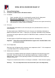
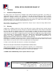
SPIRAL BEVEL GEARBOXES RANGE “N” 3. General Instructions 3.1 Installation and Maintenance Recommendations 3.1.1 Installation 1. 2. 3. 4. 5. Select a gearbox, which has a rated capacity greater than the input power Gear units are shipped dry and are fitted with a warning label Check your gear unit for damage during shipment Take care when fitting couplings; a blow on a shaft end can cause gear overmeshing. Shaft alignment is critical, check on installation 3.1.
SPIRAL BEVEL GEARBOXES RANGE “N” 4. Recommended Lubricants 4.1 Oil Specification Ambient Temperature Below +5°C +5°C to +40°C Above +40°C Gear Oil ISO 150 ISO 220 ISO 320 Mobilgear 629 or equivalent Mobilgear 630 or equivalent Mobilgear 320 or equivalent 4.1.1 Fill Quantities (average) Series No. Litres Pints 35 0.14 0.24 37 0.29 0.50 38 0.75 1.32 39 1.71 3.00 40 3.27 5.75 4.1.1 Grease Nipple / Grease filled units Use EP1 Grease e.g. Mobilux EP1 or equivalent. 4.1.
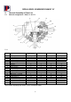
SPIRAL BEVEL GEARBOXES RANGE “N” 5. General Assembly & Parts List 5.1 General arrangement – Ratio 1:1 & 1.5:1 17 15 18 (4a) 12 9 16 10 2 8 11 6 14 13 7 5 1 4 3 5.1.1 Parts List - Ratio 1:1 & 1.
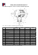
SPIRAL BEVEL GEARBOXES RANGE “N” 5.2 General arrangement – Ratio 2:1 and above and Hollow output shaft 9 18 15 4 12 5 19 2 (4a) 11 10 14 6 10 7 8 13 17 16 1 3 5.2.
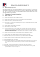
SPIRAL BEVEL GEARBOXES RANGE “N” 5.3 Motor mounting flange units. Motor mounting flange units share common components with the units detailed in 5.2, however the motor flange and input pinion are different and vary on every unit dependant upon ratio and flange size / style. For a parts list of items in a motor-flanged unit please contact Neeter Drive with the unit model number and serial number. 6. Disassembly / Assembly Instructions 6.1 Ratio 1:1 and 1.5:1 6.1.
SPIRAL BEVEL GEARBOXES RANGE “N” 6.1.16 Assemble the input shaft (1)– do not fit into gear case (9) yet. 6.1.17 Assemble the gear assembly onto one end of output shaft (2) 6.1.18 Put output shaft (2) into gear case (9), ensuring it is in the same place as when disassembled and fit rear bearing (7). 6.1.19 Fit shaft end cap (4) this is a blank cover for 2 way and 2 way reverse units or bored out cover for 3 way units. 6.1.
SPIRAL BEVEL GEARBOXES RANGE “N” 7. 7.1 Warranty Limitation of Responsibility The ratings given in this manual were compiled using standard engineering procedures. The ratings are designed to guide the customer in the selection of a unit. We do not guarantee the ratings in specific applications. Prototype testing of every application is recommended before production. Our engineering facilities are available for consultation at all times.