Installation & Maintenance Instructions EMA Electric Linear Actuators
EMA Linear Actuator Contents 1. SAFETY AUTHORISED USE ...................................................................................... 3 1.1 RESIDUAL RISK AND HAZARDS................................................................................... 3 1.2 OPERATING PERSONNEL .......................................................................................... 3 1.3 COMMISSIONING ...................................................................................................... 4 1.
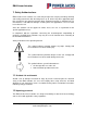
EMA Linear Actuator 1. Safety Authorised use EMA electric linear actuators are exclusively designed for carrying out lifting, lowering and feeding movements with the lifting forces up to 10 kN. Any other application other than specified or one going beyond the above mentioned capacity is unauthorised. The manufacturer is not liable for damages resulting from such applications. The user alone has to bear the risk.
EMA Linear Actuator However, the general risks of personal injury or damage to property connected with the use of such machinery cannot be completely eliminated. Therefore the units may only be assembled and operated by competent and qualified personnel and only be used for the authorised application. Therefore a careful study of this operating manual should be made before attempting to use or service the unit and particular attention should be paid to the safety instructions.
EMA Linear Actuator 2. Description EMA electric linear actuators are mainly used whenever precisely controlled lifting, lowering or feeding movements are required. The actuators consist of either a trapezoidal or ball lead screw, driven by an electric motor through spiroid gearing. The screw converts the rotary motion into linear movement. As the screw rotates, the nut extends and retracts the ram, which is attached to the load.
EMA Linear Actuator 3. Technical Data 3.1 Model I - Intermittent (less than 10 starts/day, 10 hours/day) Dynamic Load Capacity (kN) 10 5 5 5 2.5 Linear Speed (mm/min) 135 200 270 410 820 Motor (kW) Motor Frame Size Frame Size 0.18 D63 0.18 D63 0.18 D63 0.18 D63 0.18 D63 Motor Poles 6 4 6 2 2 Max. Stroke (mm) (in compression) 750 750 750 750 750 Motor Poles 6 4 2 2 2 Max. Stroke (mm) (in compression) 900 900 900 1250 1500 Motor Poles 6 2 2 6 2 Max.
EMA Linear Actuator 4. Mounting a single actuator 4.1 Unpacking and Installation Remove the EMA electric linear actuator from its container. Dispose of the packaging material and the desiccant in an environmentally friendly way. If it is necessary and in order to avoid damages, please use soft straps to transport or mount the actuator. In order to avoid damage; do not attach the straps to the inner tube but to the outer housing of the drive or to the gearbox. 4.
EMA Linear Actuator 4.3 Mounting Options Trunnion Mount Threaded Clevis End End Fork End Top Plate Standard Rear Clevis Rear Clevis at 90° Tel: +44 (0) 1358 285100 email: sales@powerjacks.com web: www.powerjacks.
EMA Linear Actuator 5. Adjusting the limit switches Electrical connections may only be performed by licensed electricians. Standard mechanical limit switches are used to cut off the electrical drive before the final position is reached. The limit switch is triggered by a cam on the lifting nut assembly. The positions of these limit switches are fixed and are not adjustable. The position is determined by the length of stroke specified by order and cannot be changed at a later date.
EMA Linear Actuator 6. Adjusting the Clutch The clutch is a device mounted on the actuator inner tube (ram) which will slip when the torque to drive the load exceeds the limit set. (refer 6.1) The clutch spindle, (6) that is attached to the load via an end fitting, is supported on bearings (8) and clamped from rotating by interlocking conical rings (7). The clamping load is applied by a locknut (5) with keyways to engage a tab washer (4).
EMA Linear Actuator 6.1 EMA Clutch General Assembly Item Number Description 1 Inner Tube (ram) 2 Distance Piece 3 Clutch Housing 4 Tab Washer 5 Lock Nut 6 Clutch Spindle 7 Conical Rings 8 Thrust Bearing 6.2 EMA Clutch Settings Actuator Rating (kg 250 250 250 250 250 250 250 500 500 500 500 500 500 500 1000 Type: T B - Lead Type Torque (mm) 3 5 6 10 12 20 25 3 5 6 10 12 20 25 5 T B T B T B B T B T B T B B B (Nm) 7.8 4.9 15.6 9.8 31.2 19.5 24.4 15.6 9.8 31.2 19.5 62.4 39 48.8 19.
EMA Linear Actuator 7. Electrical Installation 7.1 Limit Switch – Electro-Mechanical Type Item Housing Pre-Cabled Switch type Switch Actuation Max actuation speed Mechanical durability Ambient temperature Operation Storage Product conformity Enclosure Operating characteristics Insulation voltage Description Metal, compact housing, totally enclosed and sealed. 2m PVC cable 5x0.75mm2 (other cable lengths available on request). Single-pole, 1 change-over, snap action. End of plunger (metal). 0.
EMA Linear Actuator 7.3 Standard Motor Terminal Box Position 7.4 Options Delivery with mounted brake motor (DC or AC brake). Delivery with non-standard motor types e.g. servo motor, 48VDC motor. Special request, motor being supplied by the customer. 7.5 Motor Connection The electrical connections for the standard three-phase, single-phase or DC-permanentmagnet motor are within the terminal box. Appropriate rated and insulated cables require to be selected in accordance with the rated power.
EMA Linear Actuator 7.5.2 Single Phase Motor Connections This diagram is typical for motors with on board capacitors connected to the motor for the correct start and run characteristics. For motors with loose capacitors consult Power Jacks or the motor manufacturer. L1 L2 L1 L1 L1 L2 L2 L2 Forward Reverse 7.5.3 DC Motor +ve Motor -ve 8. Maintenance and Lubrication Unless otherwise specified the actuators are shipped with their full requirement of grease for normal operation.
EMA Linear Actuator 9. Parts List - General (refer to section 9.1 for EMA Electric Linear Actuator general assembly diagram) Item 1. 2. 3. 4. 5. 6. 7. 8. 9. 10. 11. 12. 13. 14. 15. 16. 17. 18. 19. 20. 21. 22. 23. 24. 25. 26. 27. 28. 29. 30. 31. 32. 33. Description Gearbox housing Rear clevis guide bush. Pinnion bearing Pinnion Pinnion bearing Shims Thrust ring Circlip Grub screw for locking bearing cap. Shims Rear bearing for gear Grub screw for locking gear to lifting screw. Gear Front bearing for gear.
EMA Linear Actuator 9.1 EMA Electric Linear Actuator (General Assembly) Tel: +44 (0) 1358 285100 email: sales@powerjacks.com web: www.powerjacks.
EMA Linear Actuator Power Jacks Ltd Balmacassie Commercial Park Ellon AB41 8BX Scotland Tel: +44 (0) 1358 285100 Email: sales@powerjacks.com www.powerjacks.