METRIC BALL SCREW JACKS SINGLE FACE MOUNTING (MECHANICAL LINEAR ACTUATORS) SPARES LIST & MAINTENANCE INSTRUCTIONS MANUAL : MM-MBS-E-02 SUPPLIED BY: POWER JACKS LIMITED
Metric Series – Ball Screw Jacks CONTENTS 1 UNIT DETAILS ....................................................................................................................................................................... 2 2 PERFORMANCE RATINGS ................................................................................................................................................. 3 2.1 PERFORMANCE OF STANDARD METRIC BALL SCREW ACTUATORS ........................................................
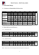
Metric Series – Ball Screw Jacks 2 Performance Ratings Performance of Standard Metric Ball Screw Jacks Actuator Model Lifting Screw Worm Gear Ratio Turn of worm for Raise of Lifting Screw Diameter Pitch Standard Optional standard Optional Maximum Input Standard Power Per Optional actuator (kW) Start-up Torque Standard at full load (Nm) † Optional Weight with base raise of 150mm (kg) Wright for each additional 25mm raise (kg) 28501 10 20mm 5mm 5 20 10 for 10mm 40 for 10mm 2802 25 25mm 5mm 10mm 6:1 24:1
Metric Series – Ball Screw Jacks 3 General Instructions 3.1 Maintenance and Installation recommendations. In order to ensure that the actuators give good service over a period of years the following precautions should be taken. 3.1.1 3.1.2 3.1.3 3.1.4 3.1.5 3.1.6 3.1.7 3.1.8 Select an actuator which has a rated capacity greater than the maximum load that may be imposed on it.
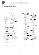
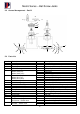
Metric Series – Ball Screw Jacks 5 General Assembly & Parts List 5.
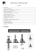
Metric Series – Ball Screw Jacks 5.2 General Arrangement – Part B 28 29 30 30 34 32 33 31 15 14 14 10 10 16 13 9 12 5.3 7 8 9 10 11 12 13 14 15 16 17 18 9 13 11 11 12 Parts List Item No 1 2 3 4 5 6 5 15 Description Shell Shell Cap Top Cap Guide Bushing Worm Shaft (6:1) Worm Shaft (8:1) Worm Shaft (24:1) Worm Gear (6:1) Worm Gear (8:1) Worm Gear (24:1) Load Bearing – Lower Load Bearing – Upper Worm Shaft Bearing Shim (0.1mm thick) Shim (0.
Metric Series – Ball Screw Jacks 6 Disassembly / Assembly Instructions (D.A.I.) 6.1 6.1.1 Translating Screw D.A.I Main Gearbox Unit IMPORTANT Disassembly should be accomplished on a clean cloth. This is particularly important when disassembling the ball nut assembly. 1. 2. 3. 4. Remove any end fixture from the end of the ball screw (17). Remove the ball screw guide bushing (4). Remove the bottom pipe (22) or top pipe (23).
Metric Series – Ball Screw Jacks Fit the knurled point set screws (supplied with detachable ends) firmly in place ensuring that point of set screws make contact with bottom of drill dimples. Secure the set screws with Loctite. 4. If actuators with keyed lifting screws are involved, and it is required to line up the clevis flats or top plate holes, etc., in a fixed relationship to the worm shaft centreline, it will be necessary to face the underside of the detachable end to obtain the required relationship.
Metric Series – Ball Screw Jacks 7 Warranty Information 7.1 Limitation of Responsibility The ratings given in this manual were compiled using standard engineering procedures. The ratings are designed to guide the customer in the selection of a unit. We do not guarantee the ratings in specific applications. Prototype testing of every application is recommended before production. Our engineering facilities are available for consultation at all times.