MAINTENANCE MANUAL C-Series Machine Screw Jack MM-SJCMS-EN-00 Operation & Maintenance Instructions with Parts List
Contents C-SERIES MACHINE SCREW JACKS SPARES LIST & MANUAL MM-SJCMS-EN-00 1 Introduction......................................................................................................................4 2 Product Code...................................................................................................................8 3 Standard Performance....................................................................................................9 4 Installation............................
1 Introduction 1.1 Translating Configurations Rod End Fork End Clevis End Lead Screw Options Top Plate 5 2. 2 x Pitch 4 3. Anti-Rotation (Keyed) 3 Bellows Boot 1. Standard 1 x Pitch 4. Stainless Steel 2 5.
Introduction 1.2 Rotating Configurations Double Hub Nut Standard Nut Safety Nut Lead Screw Options Safety Nut Double Hub 1. Standard 1 x Pitch 6 5 Bellows Boot 4 2. 2 x Pitch 3. No Pilot End 4. Stainless Steel 5. Left Hand Thread 3 6.
1 Introduction 1.3 Introduction C-Series screw jacks are exclusively designed for carrying out linear motion movements in accordance with the specification detailed in Power Jacks product information and this maintenance manual. Any other application other than specified or one going beyond the above mentioned capacity is unauthorised. The manufacturer is not liable for damages resulting from such applications. The user alone has to bear the risk.
Introduction 1.6 Operating Personnel 1.6.1 The C-Series screw jacks are designed according to state-of-the-art technology and are in line with applicable safety regulations. However, the general risks of personal injury or damage to property connected with the use of such machinery cannot be completely eliminated. Therefore the units may only be assembled and operated by competent and qualified personnel and only be used for the authorised application. 1.6.
2 Product Code 2.0 Example 1 2 3 4 5 6 - 7 8 9 10 - 11 12 13 14 - 15 16 17 18 - 19 20 21 22 - 23 24 25 C M T 0 2 5 - 0 7 5 0 - T B 1 1 - 0 0 P T - 0 0 0 B - 3 P 0 [1] - Screw Jack Type C = C-Series Screw Jack [2] - Screw Type M = Machine Screw [3] – Screw Configuration T = Translating Screw R = Rotating Screw [4,5,6] – Capacity (kN) 010 = 10kN 025 = 25kN 050 = 50kN 100 = 100 kN [7,8,9,10] – Stroke (mm) e.g.
Standard Performance Screw Jack Model4 CM-010 CM-025 CM-050 CM-100 10 25 50 100 20 30 40 Capacity (kN) Diameter (mm) Lead Screw1 Lead (mm) Option 1 Gear Ratios Maximum Input Power (kW) Start up torque at full load (Nm)2 7 Static Efficiency3 Dynamic Efficiency3 12 18 6:1 20:1 55 9 12 24 6:1 24:1 8:1 24:1 24:1 1 Turn 1mm 2mm 1mm 2mm 1.5mm 3mm 1.5mm 3mm Option 2 4 Turn 1mm 2mm 1mm 2mm 1.5mm 3mm 2mm 4mm Option 1 0.375 1.5 3 3.75 Option 2 0.19 0.375 0.
4 Installation 4.1 General Installation Notes 10 4.1.1 Before installing new parts, remove any rust preventative, protection grease etc. 4.1.2 Check before immediate installation for possible transit damage. 4.1.3 Components which have been stored for a long time (over 1 year) should be re-lubricated in working conditions before they are put into operation. 4.1.
Installation 4.2 General Instructions for fitting detachable ends on lead screws In most circumstances the screw jack is delivered with the required end fitting assembled to the unit. 4.2.1 It is important that the detachable ends are securely fixed to the lead screws and the following procedure should be adhered to. 4.2.2 Thread the detachable end on to the lead screw and tighten up as hard as possible without damaging the components. 4.2.
4 Installation 4.3 4.4 Unpacking and installation 4.3.1 Remove the C-Series screw jack(s) from their container. Dispose of the packaging material and the desiccant in an environmentally friendly way. 4.3.2 If it is necessary and in order to avoid damages, please use soft straps to transport or mount the screw jack. 4.3.3 For translating screw jacks in order to avoid damages, do not attach the straps to the lead screw but to the lead screw end fitting, cover pipe or to the screw jacks gearbox.
Installation 4.4.11 Drive Motor 4.4.11.1 Power Jacks recommend that when you purchase a screw jack requiring a motor mounted directly to the screw jack this is purchased as a complete item from Power Jacks. The motor is then pre-assembled to the screw jack. If you have opted to fit a motor yourself below is a typical procedure for common motor types. 4.4.11.2 Before mounting the drive motor, check the direction of rotation of the screw jack drive shafts relative to the linear motion of its lead screw.
4 Installation 4.4.13 Limit Switches – Rotary Cam Type (RLS) 4.4.13.1 4.4.13.2 4.5 Power Jacks recommend that when you purchase a screw jack requiring a Rotary cam type Limit Switch (RLS) mounted directly to the screw jack this is purchased as a complete item from Power Jacks. The RLS unit is then pre-assembled to the screw jack. If you have opted to fit a RLS unit yourself below is a typical procedure for common RLS unit types.
Operation 5.1 5.2 Operational Recommendations 5.1.1 Select a screw jack which has a rated capacity greater than the maximum load that may be imposed on it. 5.1.2 The screw jacks should have a greater raise than is needed in the actual installation. Should it be necessary to operate the screw jacks at the extreme limits of travel it should be done cautiously. 5.1.
5 Operation 5.2.3 Anti-Backlash Screw Jack – When To Use For reduced axial backlash of the lead screw in the screw jack select a model with the "AntiBacklash" mechanism. This is typically used when the load direction changes from tension to compression and minimal axial backlash is required. This design is only available for translating screw jacks. It can be combined with Anti-Rotation mechanism as well. 5.2.
Operation 5.2.11 Shock Loads on a Screw Jack Shock loads should be eliminated or reduced to a minimum, if they cannot be avoided, the screw jack model selected should be rated at twice the required static load. For severe shock load applications, use the E-Series, S-Series or M-series screw jacks, the load bearings here can be replaced with heat-treated steel thrust rings which is an option available from Power Jacks. Note this will increase the input torque by approximately 100%. 5.2.
5 Operation 5.2.15 Side Loads on a Screw Jack Screw jacks are designed primarily to move and position loads and any side loads (loads not acting axially on lead screw) should be avoided. The units will withstand some side loads, depending on the diameter of the lifting screw and the extended length of the lifting screw. Where side loads are present, the loads should be guided and the guides, rather than the screw jacks, should take the side loads - particularly when long raises are involved.
Operation 5.2.21 Corrosion Resistant Properties Screw Jacks can be supplied with alternative materials and/or paint specifications for high corrosive areas. These options include stainless steel, chrome plating, Electro-nickel plating, epoxy paint, etc. Check the unit specification is suitable before installation. 5.2.
5 Operation 20 5.2.28 Connecting Screw Jacks in Series The number of screw jacks that can be connected in series is limited by input torque requirements on the first worm shaft in the line. For the C-Series the torque on the worm shaft of the first screw jack should not exceed 300% of its rated full load torque (this does not include the 200kN screw jacks which are rated at 200%). 5.2.
Maintenance 6.1 General Maintenance Notes 6.1.1 Maintenance and replacement work must be done by an expert maintenance technicians trained in the observance of applicable laws on health and safety at work and the special ambient problems attendant on the installation. 6.1.
6 Maintenance 6.2 Regular Maintenance Also refer to section 6.3 6.2.1 Lubrication Of The Screw Jack 6.2.1.1 The screw jacks are shipped packed with grease (unless otherwise called for) which should be sufficient for one month of normal operation. 6.2.1.2 IMPORTANT NOTE – Lubricant suitability is dependent on duty cycle and ambient temperature. However in general recommended lubricants in section 7 are suitable for operation in an ambient temperature of -10ºC to +50ºC.
Maintenance 6.4 6.3.4 Check all bolted joints/couplings for wear, deformation or corrosion and tighten them down fully without over tightening. 6.3.5 A periodic check of backlash between lead screw and worm gear (translating screw jacks) or lead screw and nut (rotating screw jacks) is recommended to check wear on internal threads of worm gear. Backlash in excess of 25% thread thickness indicates that a replacement will be necessary to replace the worm gear / nut assembly. 6.3.
6 Maintenance 6.6 6.7 6.5.8.6 When installing the worm shaft, use shims to establish the correct axial float for the bearings Installed. 6.5.8.7 When screwing in the shell cap, establish the correct tightening torque by screwing down and backing off the shell cap until the torque figure for the model is achieved. 6.5.8.8 Lock the shell cap in place with locking fasteners. 6.5.8.9 For fasteners without spring lock washers use a chemical thread locking compound (e.g. Loctite). Replacing Parts 6.6.
Maintenance 6.9.2.2 6.9.3 6.10 Flush a unit’s interior thoroughly with a light solvent before refilling with new lubricant. Warning 6.9.3.1 Provide adequate ventilation during the use of cleaning agents; avoid prolonged breathing of fumes and contact with skin. 6.9.3.2 Use clean hot water or a soap solution for general cleaning of painted surfaces. 6.9.3.3 Dry parts thoroughly after cleaning. Painting 6.10.
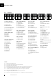
7 Recommended Lubricants 7 Recommended Lubricants Table 1 - Normal Operation Manufacturer Lubricant Castrol Esso Gulf Mobiloil Power Petroleum Regent Shell Spheerol EPL2 Beacon EP2 Gulfcrown EP2 Mobilux EP2 BP Energrease LC2 Texaco EP2 Gadus S2V220AC2 (Alvania WR2) Table 2 - Arduous Operation Manufacturer Lubricant Castrol Esso Mobiloil Power Petroleum Regent Spheerol LMM2 Beacon EP2 Moly Mobilgrease XHP222 Special BP Energrease L2 1M Molytex 2 Shell Greases 5826 (Overseas) Shell Alvania HDX2 Sh
Spare Parts 8.1 Recommendations 8.1.1 C-Series screw jacks are fully supported by Power Jacks. Spare parts and repairs are available. 8.1.2 It is recommended that when a screw jack is used in a production critical environment where the cost of downtime far exceeds the cost of the screw jack a complete spare screw jack unit is stocked by the customer. This allows the worn/damaged unit to be returned to Power Jacks for repair by trained personnel.
9 Storage & Warehousing 9.1 General Storage Recommendations Recommendations for storing the products are indicated below: 9.2 9.1.1 Store in a clean and dry environment, free from dirt and dust. 9.1.2 Screw Jack Storage Temperature: -10°C to +50°C. 9.1.3 Do not store the unit in excessively humid conditions or where it is exposed to the weather (do not store outdoors). 9.1.4 Do not place product directly on the ground. 9.1.
Disposal of Units 10.1 General Disposal Guidance 10.1.1 This must only be done by operators trained in the observance of applicable laws on health and safety at work. 10.1.2 Do not dump non-biodegradable products, lubricants and non-ferrous materials (rubber, PVC, resins, etc.) into the environment. Dispose of all such materials as stipulated by applicable environmental protection legislation. 10.1.
11 Warranty 11.1 Warranty Definitions When used in these conditions the following words have the meanings set out opposite them below: Company: Contract: Customer: Goods: Writing: 11.2 Power Jacks Limited The contract between the Company and the Customer for the supply of the Goods.
General Assembly & Parts List 12.
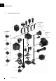
12 General Assembly & Parts List 12.2 Rotating 32 38 30/31 2 8 5 33 5 15 4 14 11 13 15 11 8 6 12 10 34 35 3 6 9 32 7 www.powerjacks.
General Assembly & Parts List 12.3 Translating 2 8 5 20/21 4 5 14 15 11 13 15 11 8 7 6 12 10 9 1 22 3 6 9 7 23 www.powerjacks.
12 General Assembly & Parts List 12.4 Translating Anti-Backlash 55 51 5 8 20/21 52 54 5 53 14 15 11 13 15 11 8 6 12 10 22 3 6 9 7 23 34 www.powerjacks.
General Assembly & Parts List 12.5 Translating Anti-Rotation (Keyed) 73 74/75 70 8 5 71/72 4 14 5 15 11 13 15 11 8 7 6 12 10 9 1 22 3 6 9 7 23 www.powerjacks.
12 General Assembly & Parts List 12.6 Translating Anti-Backlash & Anti-Rotation (Keyed) 55 51 5 8 20/21 52 54 5 53 14 15 11 13 15 11 8 6 12 10 73 80 3 6 9 7 22 23 36 www.powerjacks.
General Assembly & Parts List 12.7 Accessories & Options Anti-Backlash Anti-Rotation (Keyed) Safety Nut Trunnion Mounts End Fittings Limit Switches Motor Adaptors Corrosion Protection Rotary Limit Switch Adaptor Double Hub Nut Drives Secondary Guide www.powerjacks.
Notes 38 www.powerjacks.
Power Jacks are an industry leader in the manufacture of quality industrial lifting, positioning,material handling and power transmission equipment. The products are supplied globally to most industry sectors including nuclear, water, oil & gas, chemical, defence, steel, aluminium, automotive, and others. PRECISION SCREW JACKS . ELECTRIC LINEAR ACTUATORS . PLANETARY ROLLER SCREWS . SPIRAL BEVEL GEARBOXES .