
Datasheet


TOP242-250
19
I
4/03
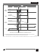
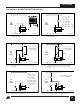
Figure 32. Line Sensing for Under-Voltage Only (Overvoltage
Disabled).
PI-2510-040501
DC
Input
Voltage
+
-
DM
S
C
V
UV
= R
LS
x I
UV
For Value Shown
V
UV
= 100 VDC
R
LS
6.2 V
2 MΩ
22 kΩ
CONTROL
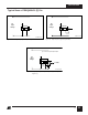
Figure 33. Line Sensing for Overvoltage Only (Under-Voltage
Disabled). Maximum Duty Cycle will be reduced at
Low Line.
Figure 34. Externally Set Current Limit.
PI-2517-040501
DC
Input
Voltage
+
-
DM
S
C
For R
IL
= 12 kΩ
I
LIMIT
= 69%
CONTROL
R
IL
See fig. 55 for other
resistor values (R
IL
)
For R
IL
= 25 kΩ
I
LIMIT
= 43%
to select different
I
LIMIT
values
PI-2516-040501
DC
Input
Voltage
+
-
DM
S
C
V
OV
= I
OV
x
R
LS
For Values Shown
V
OV
= 450 VDC
CONTROL
R
LS
1N4148
2 MΩ
30 kΩ
Figure 30. Three Terminal Operation (MULTI-FUNCTION
Features Disabled).
PI-2508-081199
DC
Input
Voltage
+
-
D
S
C
CONTROL
M
C
DS
CD S
S
SS
M
PI-2509-040501
DC
Input
Voltage
+
-
DM
S
C
V
UV
= I
UV
x R
LS
V
OV
=
I
OV
x
R
LS
For R
LS
= 2 MΩ
V
UV
= 100 VDC
V
OV
=
450 VDC
DC
MAX
@100 VDC = 78%
DC
MAX
@375 VDC = 38%
CONTROL
R
LS
2 MΩ
Typical Uses of MULTI-FUNCTION (M) Pin
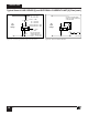
Figure 35. Current Limit Reduction with Line Voltage.
PI-2518-040501
DC
Input
Voltage
+
-
DM
S
C
CONTROL
R
IL
R
LS
2.5 MΩ
6 kΩ
100% @ 100 VDC
63% @ 300 VDC
I
LIMIT
=
I
LIMIT
=
Figure 31. Line Sensing for Undervoltage, Over-Voltage and
Line Feed Forward.