
Datasheet


TOP242-250
37
I
4/03
I
LIMIT
A
Conditions
(Unless Otherwise Specified)
See Figure 53
SOURCE = 0 V; T
J
= -40 to 125 °C
Min Typ Max
Parameter
Symbol
Units
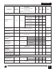
CIRCUIT PROTECTION
FREQUENCY INPUT
FREQUENCY Pin
Threshold Voltage
FREQUENCY Pin
Input Current
V
F
= V
C
V
F
I
F
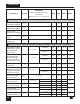
Self Protection
Current Limit
(See Note C)
See Note B
2.9 V
10 40 100 µA
MULTI-FUNCTION (M), LINE-SENSE (L) AND EXTERNAL CURRENT LIMIT (X) INPUTS
Remote ON Delay
Remote OFF
Setup Time
t
R(ON)
t
R(OFF)
From Remote On to Drain Turn-On
See Note B
Minimum Time Before Drain Turn-On
to Disable Cycle
See Note B
2.5 µs
2.5 µs
TOP242 P/G
TOP242 Y/R/F
T
J
= 25 °C
TOP243 P/G
T
J
= 25 °C
TOP243 Y/R/F
T
J
= 25 °C
TOP244 P/G
T
J
= 25 °C
TOP244 Y/R/F
T
J
= 25 °C
TOP245 Y/R/F
T
J
= 25 °C
TOP246 Y/R/F
T
J
= 25 °C
TOP247 Y/R/F
T
J
= 25 °C
TOP248 Y/R/F
T
J
= 25 °C
Internal
di/dt=90 mA/µs
Internal
di/dt=150 mA/µs
Internal
di/dt=180 mA/µs
Internal
di/dt=200 mA/µs
Internal
di/dt=270 mA/µs
Internal
di/dt=360 mA/µs
Internal
di/dt=540 mA/µs
Internal
di/dt=720 mA/µs
Internal
di/dt=900 mA/µs
0.418 0.45 0.481
0.697 0.75 0.802
0.837 0.90 0.963
0.930 1.00 1.070
1.256 1.35 1.445
1.674 1.80 1.926
2.511 2.70 2.889
3.348 3.60 3.852
4.185 4.50 4.815
T
J
= 25 °C
See Figure 70
V
DRAIN
= 150 V
X, L or M Pin
Floating
Maximum Duty
Cycle Reduction
Onset Threshold
Current
Remote OFF
DRAIN Supply
Current
L or M Pin Shorted
to CONTROL
I
L (DC)
or
I
M (DC)
I
D(RMT)
40 60 75
0.6 1.0
1.0 1.6
µA
mA