
Datasheet


TOP242-250
28
I
4/03
General Information & Table of Contents
Product Selector Guide 1
Data Sheets 2
Application Notes 3
Design Ideas 4
Design Tools 5
Quality and Reliability 6
Package Information 7
DPA-Switch
DC-DC Seminar 8
LinkSwitch
&
TinySwitch-II
AC-DC Seminar 9
TOPSwitch-GX
AC-DC Seminar 10
Sales Representatives and Distributors 11
Table 4 (cont). Comparison Between TOPSwitch-II and TOPSwitch-GX. *Not available
Function
TOPSwitch-FX
TOPSwitch-GX TOPSwitch-GX
Advantages
Light Load Operation Cycle skipping Frequency and Duty Cycle • Improves light load efficiency
reduction • Reduces no-load consumption
Line Sensing/Externally Line sensing and Line sensing and externally • Additional design flexibility allows all
Set Current Limit externally set set current limit possible features to be used simultaneously
(Y, R and F Packages) current limit simultaneously
mutually (functions split onto
exclusive (M pin) L and X pins)
Current Limit 100-40% 100-30% • Minimizes transformer core size
Programming in highly continuous designs
Range
TOPSwitch-FX
vs.
TOPSwitch-GX
Table 5 compares the features and performance differences
between TOPSwitch-GX and TOPSwitch-FX. Many of the new
features eliminate the need for additional discrete components.
Other features increase the robustness of design allowing cost
savings in the transformer and other power components.
Function
TOPSwitch-II TOPSwitch-GX
Figures
TOPSwitch-GX
Advantages
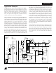
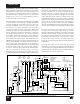
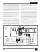
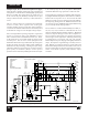
Remote ON/OFF N/A* Single transistor 11, 22, • Fast on/off (cycle by cycle)
or optocoupler 23, 24, • Active-on or active-off control
interface or manual 25, 26, • Low consumption in remote off state
switch 27, 29, • Active-on control for fail-safe
36, 37, • Eliminates expensive in-line on/off
38, 39, switch
40 • Allows processor controlled turn
on/off
• Permits shutdown/wake-up of
peripherals via LAN or parallel port
Synchronization N/A* Single transistor • Synchronization to external lower
or optocoupler frequency signal
interface • Starts new switching cycle on
demand
Thermal Shutdown 125 °C min. Hysteretic 130 °C•Automatic recovery from thermal
Latched min. Shutdown (with fault
75 °C hysteresis) • Large hysteresis prevents circuit
board overheating
Current Limit Tolerance ±10% (@25 °C) ±7% (@25 °C) • 10% higher power capability due to
-8% (0 °C to100 °C) -4% Typical tighter tolerance
(0 °C to 100 °C)
DRAIN DIP 0.037" / 0.94 mm 0.137" / 3.48 mm • Greater immunity to arcing as a
Creepage SMD 0.037" / 0.94 mm 0.137" / 3.48 mm result of build-up of dust, debris and
at Package TO-220 0.046" / 1.17 mm 0.068" / 1.73 mm other contaminants
DRAIN Creepage at 0.045" / 1.14 mm 0.113" / 2.87 mm • Preformed leads accommodate
PCB for Y, R and F (R and F (preformed leads) large creepage for PCB layout
Packages Package N/A*) • Easier to meet Safety (UL/VDE)
Table 5. Comparison Between TOPSwitch-FX and TOPSwitch-GX. (continued on next page)