
Datasheet


TOP242-250
20
I
4/03
General Information & Table of Contents
Product Selector Guide 1
Data Sheets 2
Application Notes 3
Design Ideas 4
Design Tools 5
Quality and Reliability 6
Package Information 7
DPA-Switch
DC-DC Seminar 8
LinkSwitch
&
TinySwitch-II
AC-DC Seminar 9
TOPSwitch-GX
AC-DC Seminar 10
Sales Representatives and Distributors 11
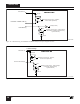
PI-2522-040501
DC
Input
Voltage
+
-
D
S
C
R
MC
45 kΩ
M
CONTROL
Q
R
Q
R
can be an optocoupler
output or can be replaced
by a manual switch.
ON/OFF
47 kΩ
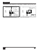
Figure 37. Active-off Remote ON/OFF. Maximum Duty Cycle will
be Reduced.
Figure 36. Active-on (Fail Safe) Remote ON/OFF.
PI-2519-040501
DC
Input
Voltage
+
-
D
S
C
Q
R
ON/OFF
M
CONTROL
Q
R
can be an optocoupler
output or can be replaced
by a manual switch.
47 kΩ
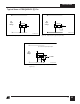
PI-2523-040501
DC
Input
Voltage
+
-
D
S
C
R
LS
M
For R
LS
= 2 MΩ
V
UV
= 100 VDC
V
OV
= 450 VDC
CONTROL
Q
R
2 MΩ
Q
R
can be an optocoupler
output or can be replaced
by a manual switch.
ON/OFF
47 kΩ
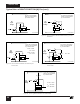
Figure 40. Active-off Remote ON/OFF with LINE-SENSE.
Figure 39. Active-off Remote ON/OFF with Externally Set
Current Limit.
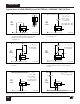
PI-2521-040501
DC
Input
Voltage
+
-
D
S
C
R
IL
R
MC
24 kΩ
12 kΩ
M
CONTROL
Q
R
2R
IL
R
MC
=
Q
R
can be an optocoupler
output or can be replaced
by a manual switch.
ON/OFF
47 kΩ
Figure 38. Active-on Remote ON/OFF with Externally Set
Current Limit.
PI-2520-040501
DC
Input
Voltage
+
-
D
S
C
Q
R
R
IL
M
CONTROL
12 kΩ
For R
IL
=
I
LIMIT
= 69%
Q
R
can be an optocoupler
output or can be replaced
by a manual switch.
ON/OFF
47 kΩ
25 kΩ
For R
IL
=
I
LIMIT
= 43%
Typical Uses of MULTI-FUNCTION (M) Pin (cont.)