
Datasheet


TOP242-250
35
I
4/03
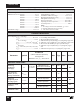
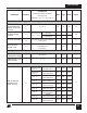
CONTROL FUNCTIONS
Conditions
(Unless Otherwise Specified)
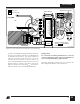
See Figure 53
SOURCE = 0 V; T
J
= -40 to 125 °C
Min Typ Max
Parameter
Symbol
Units
See Note A
See Figure 7
T
J
= 25 °C
I
C
= 4 mA; T
J
= 25 °C
See Figure 51
l
B
l
C(OFF)
Z
C
PWM Gain
Temperature Drift
External Bias
Current
CONTROL
Current at 0%
Duty Cycle
Dynamic
Impedance
Dynamic
Impedance
Temperature Drift
CONTROL Pin
Internal Filter Pole
%/mA/°C
mA
mA
Ω
%/°C
kHz
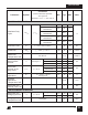
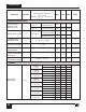
SHUTDOWN/AUTO-RESTART
V
C
= 0 V
V
C
= 5 V
l
C (CH)
CONTROL Pin
Charging Current
Charging Current
Temperature Drift
mA
%/°C
-5.0 -3.5 -2.0
-3.0 -1.8 -0.6
0.5
T
J
= 25 °C
See Note A
Soft Start Time t
SOFT
T
J
= 25 °C; DC
MIN
to
DC
MAX
10 15 ms
PWM Gain DC
reg
I
C
= 4 mA; T
J
= 25 °C -28 -23 -18 %/mA
TOP242-245
TOP246-249
TOP250
TOP242-245
TOP246-249
TOP250
-0.01
1.2 2.0 3.0
1.6 2.6 4.0
1.7 2.7 4.2
6.0 7.0
6.6 8.0
7.3 8.5
10 15 22
0.18
7
I
L
≤
I
L (DC)
or I
M
≤ I
M(DC)
I
L
or I
M
= 190 µA
TOP242-245
I
L
or I
M
= 100 µA
TOP242-245
I
L
or I
M
= 190 µA
TOP246-250
I
L
or I
M
= 100 µA
TOP246-250
Maximum Duty
Cycle
DC
MAX
I
C
= I
CD1
75 78 83
28 38 50
66.5
33 41.3 49.5
60 66.8 73.5
%