
Datasheet


TOP242-250
16
I
4/03
General Information & Table of Contents
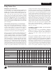
Product Selector Guide 1
Data Sheets 2
Application Notes 3
Design Ideas 4
Design Tools 5
Quality and Reliability 6
Package Information 7
DPA-Switch
DC-DC Seminar 8
LinkSwitch
&
TinySwitch-II
AC-DC Seminar 9
TOPSwitch-GX
AC-DC Seminar 10
Sales Representatives and Distributors 11
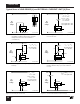
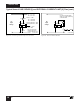
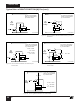
Typical Uses of LINE-SENSE (L) and EXTERNAL CURRENT LIMIT (X) Pins
XF
PI-2617-050100
DC
Input
Voltage
+
-
D
CS D
S
C
CONTROL
L
CLXS F D
PI-2618-040501
DC
Input
Voltage
+
-
D
S
C
CONTROL
L
2MΩR
LS
V
UV
= I
UV
x R
LS
V
OV
=
I
OV
x
R
LS
For R
LS
= 2 MΩ
V
UV
= 100 VDC
V
OV
=
450 VDC
DC
MAX
@100 VDC = 78%
DC
MAX
@375 VDC = 38%
PI-2510-040501
DC
Input
Voltage
+
-
DM
S
C
V
UV
= R
LS
x I
UV
For Value Shown
V
UV
= 100 VDC
R
LS
6.2 V
2 MΩ
22 kΩ
CONTROL
PI-2620-040501
DC
Input
Voltage
+
-
D
S
C
CONTROL
L
2 MΩ
30 kΩ
R
LS
1N4148
V
OV
= I
OV
x
R
LS
For Values Shown
V
OV
= 450 VDC
X
PI-2623-040501
DC
Input
Voltage
+
-
D
S
C
R
IL
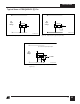
For R
IL
= 12 kΩ
I
LIMIT
= 69%
See fig. 55 for other
resistor values (R
IL
)
For R
IL
= 25 kΩ
I
LIMIT
= 43%
CONTROL
X
PI-2624-040501
DC
Input
Voltage
+
-
D
S
C
2.5 MΩR
LS
6 kΩ
R
IL
100% @ 100 VDC
63% @ 300 VDC
I
LIMIT
=
I
LIMIT
=
CONTROL
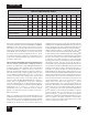
Figure 16. Three Terminal Operation (LINE-SENSE and
EXTERNAL CURRENT LIMIT Features Disabled.
FREQUENCY Pin can be tied to SOURCE or
CONTROL Pin).
Figure 17. Line-Sensing for Under-Voltage, Overvoltage and
Line Feed Forward.
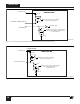
Figure 18. Line-Sensing for Under-Voltage Only (Overvoltage
Disabled).
Figure 19. Line-Sensing for Overvoltage Only (Under-Voltage
Disabled). Maximum Duty Cycle will be reduced at
Low Line.
Figure 20. Externally Set Current Limit.
Figure 21. Current Limit Reduction with Line Voltage.