
Datasheet


TOP221-227
D
7/01
16
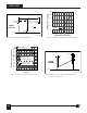
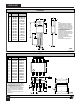
The following precautions should be followed when testing
TOPSwitch by itself outside of a power supply. The schematic
shown in Figure 14 is suggested for laboratory testing of
TOPSwitch.
When the DRAIN supply is turned on, the part will be in the
Auto-restart mode. The CONTROL pin voltage will be
oscillating at a low frequency from 4.7 to 5.7 V and the DRAIN
is turned on every eighth cycle of the CONTROL pin oscillation.
If the CONTROL pin power supply is turned on while in this
BENCH TEST PRECAUTIONS FOR EVALUATION OF ELECTRICAL CHARACTERISTICS
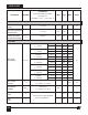
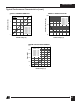
Typical Performance Characteristics
Auto-restart mode, there is only a 12.5% chance that the control
pin oscillation will be in the correct state (DRAIN active state)
so that the continuous DRAIN voltage waveform may be
observed. It is recommended that the V
C
power supply be
turned on first and the DRAIN power supply second if continuous
drain voltage waveforms are to be observed. The 12.5% chance
of being in the correct state is due to the 8:1 counter. Temporarily
shorting the CONTROL pin to the SOURCE pin will reset
TOPSwitch, which then will come up in the correct state.
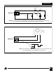
2
1.2
1.6
0
0 20 40 60 80 100
DRAIN Voltage (V)
CONTROL Pin
Charging Current (mA)
I
C
vs. DRAIN VOLTAGE
PI-1145-103194
0.4
0.8
V
C
= 5 V
1.1
1.0
0.9
-50 -25 0 25 50 75 100 125 150
Junction Temperature (°C)
Breakdown Voltage (V)
(Normalized to 25 °C)
BREAKDOWN vs. TEMPERATURE
PI-176B-051391
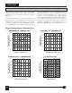
1.2
1.0
0.8
0.6
0.4
0.2
0
-50 -25 0 25 50 75 100 125 150
Junction Temperature (°C)
CURRENT LIMIT vs. TEMPERATURE
PI-1125-033001
Current Limit
(Normalized to 25 °C)
1.2
1.0
0.8
0.6
0.4
0.2
0
-50 -25 0 25 50 75 100 125 150
Junction Temperature (°C)
FREQUENCY vs. TEMPERATURE
PI-1123A-033001
Output Frequency
(Normalized to 25 °C)