
Datasheet


TOP221-227
D
7/01
14
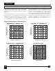
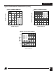
Figure 11. TOPSwitch CONTROL Pin I-V Characteristic.
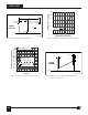
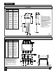
Figure 10. TOPSwitch Duty Cycle Measurement.
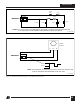
Figure 12. Self-protection Current Limit Envelope.
PI-2031-040401
∆I
D
100 ns
t
LEB
DRAIN
CURRENT
0 A
Figure 13. Example of
∆
I
D
on Drain Current Waveform with
Saturated Transformer.
0.8
1.3
1.2
1.1
0.9
0.8
1.0
0
012 6 83
Time (µs)
DRAIN Current (normalized)
PI-2022-033001
45 7
0.7
0.6
0.5
0.4
0.3
0.2
0.1
I
LIMIT(MAX)
@ 25 °C
I
LIMIT(MIN)
@ 25 °C
I
INIT(MIN)
@ 85 VAC
I
INIT(MIN)
@ 265 VAC
t
LEB
(Blanking Time)
PI-2039-040401
DRAIN
VOLTAGE
HV
0 V
90%
10%
90%
t
2
t
1
D =
t
1
t
2
120
100
80
40
20
60
0
0246810
CONTROL Pin Voltage (V)
CONTROL Pin Current (mA)
PI-1939-091996
1
Slope
Dynamic
Impedance
=