
Datasheet


TOP221-227
D
7/01
13
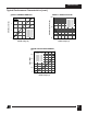
V
C(SHUNT)
I
CD1
I
CD2
36
5.5 5.7 6.0
±50
0.6 1.2 1.6
0.7 1.4 1.8
0.5 0.8 1.1
DRAIN Supply
Voltage
Shunt Regulator
Voltage
Shunt Regulator
Temperature Drift
CONTROL Supply/
Discharge Current
V
V
ppm/°C
mA
OUTPUT (cont.)
NOTES:
A. For specifications with negative values, a negative temperature coefficient corresponds to an increase in
magnitude with increasing temperature, and a positive temperature coefficient corresponds to a decrease in
magnitude with increasing temperature.
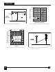
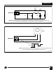
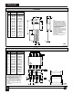
B. The breakdown voltage and leakage current measurements can be accomplished as shown in Figure 15 by using
the following sequence:
i. The curve tracer should initially be set at 0 V. The base output should be adjusted through a voltage sequence
of 0 V, 6.5 V, 4.3 V, and 6.5 V, as shown. The base current from the curve tracer should not exceed 100 mA. This
CONTROL pin sequence interrupts the Auto-restart sequence and locks the TOPSwitch internal MOSFET in the
OFF State.
ii. The breakdown and the leakage measurements can now be taken with the curve tracer. The maximum
voltage from the curve tracer must be limited to 700 V under all conditions.
C. It is possible to start up and operate TOPSwitch at DRAIN voltages well below 36 V. However, the CONTROL pin
charging current is reduced, which affects start-up time, auto-restart frequency, and auto-restart duty cycle. Refer
to the characteristic graph on CONTROL pin charge current (I
C
) vs. DRAIN voltage for low voltage operation
characteristics.
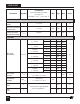
Conditions
(Unless Otherwise Specified)
See Figure 14
SOURCE = 0 V; T
J
= -40 to 125 °C
Min Typ Max
Parameter
Symbol
Units
See Note C
I
C
= 4 mA
Output TOP221-224
MOSFET Enabled TOP225-227
Output MOSFET Disabled