
Datasheet


TOP221-227
D
7/01
11
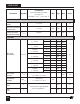
5.7
4.4 4.7 5.0
0.6 1.0
259
258
1.2
0.23 0.25 0.28
0.45 0.50 0.55
0.90 1.00 1.10
1.35 1.50 1.65
1.80 2.00 2.20
2.25 2.50 2.75
2.70 3.00 3.30
0.75 x
I
LIMIT(MIN)
180
V
C(AR)
I
LIMIT
I
INIT
t
LEB
SHUTDOWN/AUTO-RESTART (cont.)
Auto-restart
Threshold Voltage
UV Lockout
Threshold Voltage
Auto-restart
Hysteresis Voltage
Auto-restart
Duty Cycle
Auto-restart
Frequency
Self-protection
Current Limit
Initial Current
Limit
Leading Edge
Blanking Time
CIRCUIT PROTECTION
V
V
V
%
Hz
A
A
ns
≤ 85 VAC
(Rectified Line Input)
265 VAC
(Rectified Line Input)
0.6 x
I
LIMIT(MIN)
Conditions
(Unless Otherwise Specified)
See Figure 14
SOURCE = 0 V
; T
J
= -40 to 125 °C
Min Typ Max
Parameter
Symbol
Units
TOP221-222
TOP223-227
S1 open
S1 open
S1 open
S1 open
S1 open
di/dt = 40 mA/µs, TOP221Y
T
J
= 25 °C TOP221P or G
di/dt = 80 mA/µs, TOP222Y
T
J
= 25 °C TOP222P or G
di/dt = 160 mA/µs, TOP223Y
T
J
= 25 °C TOP223P or G
di/dt = 240 mA/µs, TOP224Y
T
J
= 25 °C TOP224P or G
di/dt = 320 mA/µs,
TOP225Y
T
J
= 25 °C
di/dt = 400 mA/µs,
TOP226Y
T
J
= 25 °C
di/dt = 480 mA/µs,
TOP227Y
T
J
= 25 °C
See Figure 12
T
J
= 25 °C
I
C
= 4 mA,
T
J
= 25 °C