
Assembly Instruction

Page 2/5
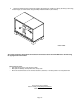
A
A
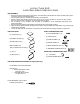
ASSEMBLY INSTRUCTIONS:
1. Insert (4) Wood Dowels (H) into the pre-drilled holes on the Side Panels (B) and (BB) (Figure 1). Then, fasten the (4)
Cam Lock Bolts (G) into the predrilled holes in Top Panel (A) and Bottom Panel (AA), using the Phillips Head Screwdriver
as shown in Figure 2. Do not over tighten the Cam Lock Bolts or the Cam Locks will not properly engage in
Steps 2 and 3.
Figure 1 Figure 2
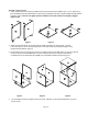
2. Attach the Right Side Panel (B) and Left Side Panel (BB) onto Bottom End Panel (AA), as shown.
Insert Cam Lock (F) into the corresponding holes on the Side Panels (B) and (BB) and tighten using
Phillips Head Screwdriver. (Figure 3)
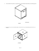
3. Insert the Back panel (D) through the U-groove on the Side panels (B) and (BB) (Figure 4). Place the Top End
Panel (A) onto the semi-assembled base, as shown. Insert the Cam Lock (F) into the corresponding
pre-drilled holes on the Side Panels (B) and (BB), then use Phillips screwdriver to fasten (Figure 5).
B
D
A
A
B
B
B
Figure 3 Figure 4 Figure 5
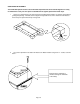
4. Use the Phillips screwdriver to tighten all the Cam Locks. If desired, use the (8) Espresso Sticker (J) to cover
the Cam Locks.
B
BB