
Instruction Manual

77
PFC-9000 • 5403535 • REV G • 9/08
Appendix A - Module Specications and Features
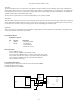
Main Fire Alarm Chassis PFC-9000
ELECTRICAL RATINGS:
- AC Line Voltage: 102 to 132 VAC 4 Amps or 204 to 264 VAC (primary)
- Power Supply ratings: 12 Amps. max. (secondary)
- For Notication Circuits: 24VDC unltered 10 Amps. max.
- Charging capability: 17-40 AH batteries
GENERAL:
- One Analog Loop capable of monitoring 127 Sensors and Modules.
Power Limited: 40 VDC, 400 mA max, max loop resistance 50 ohms.
- 4 Style Y or Z (Class B or A) Indicating Circuits; congurable as strobes or audibles. Terminals are labeled “IND”.
Power Limited: 24 VDC unltered 1.7 A @ 49
o
C per Circuit
- Displays and Controls for all Common Functions
- Optional PR-5000 City Tie Module, UDACT-9100
- Aux. Power Supply (for Remote Annunciators). Terminals are labeled “AUX PWR”.
Power Limited: 24 VDC unltered 1.7 A @ 49°C
- Resettable 4-Wire Smoke Supplies. Terminals are labeled “4-WIRE”.
Power Limited: 22 VDC, 400 mA max., 5mV ripple
- 1 RS-485 Connection for Remote Annunciators or graphic drivers. Power Limited to 300 mA. Terminals are labeled
“RS485”.
- SLA-127P Single Loop Adder provides an additional 127 points.
- DLA-254P Dual Loop Adder provides an additional 254 points.
- Auxiliary relays: (resistive loads)
Must be connected to a Listed Power Limited Source of Supply. Terminals are labeled “ALARM, TROUBLE, SUPV”.
Common Alarm: Form C, 1 Amp, 28 VDC
Common Supv: Form C, 1 Amp, 28 VDC
Common Trouble: Form C, 1 Amp, 28 VDC
- Micro-controller Based Design.
- Fully Congurable with PC Software.
- Full Walk-Test function, Silent and Audible