
Instruction Manual

28
PFC-9000 • 5403535 • REV G • 9/08
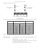
IDC-9004 4 Zone Notication Circuit Adder Card
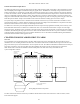
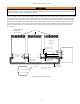
The IDC-9004 provides four additional zones of Class A (Style Z) or Class B (Style Y) notication circuits. The IDC-9004 is
programmed in the conguration software as either a strobe or signal circuit. When programmed as a signal circuit, that circuit
will operate at the same rate as programmed in the conguration software.
Each circuit of the IDC-9004 are power limited and have a maximum of 1.7 Amps. Each circuit can be programmed to be
silenceable (deactivated) or nonsilenceable. All terminals are removeable for easy wiring.
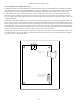
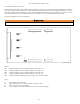
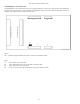
Jumpers
JW1 Continuity Jumper installed only if device is the last circuit adder installed
JW2 Jumper for ability to deactivate the bells on Circuit 1
JW3 Jumper for ability to deactivate the bells on Circuit 2
JW4 Jumper for ability to deactivate the bells on Circuit 3
JW5 Jumper for ability to deactivate the bells on Circuit 4
JW11 Terminals for Bell Cut Relay
Plugs
P1 Data cable for next circuit adder
P2 Data cable attached to previous circuit adder or main re alarm
P3 Power connector to next circuit adder
P4 Power connector to P8 of re alarm board or previous circuit adder module
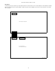
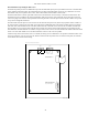
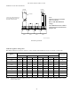
FIELD WIRING TERMINALS
JW5
JW4
JW3
JW2
JW1
P1 P3
P2 P4
JW11
DWG# PFC-9000-18
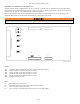
Failure to connect notication circuits to notication appliances will result in occupants not being notied to evacuate or relocate.