
User's Manual


3
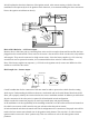
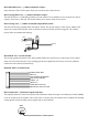
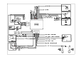
We will explain the three basic functions of the ignition switch, when remote starting a vehicle. Since this
installation will require analysis of the ignition switch functions, we recommend making the three connections
blow at the ignition switch harness directly.
ORANGE ACC
BROWN IGN2
YELLOW IGN1
PURPLE (START)
RED +12V
RED +12V
30A
FUSE
FUSE BOX
30A
FUSE
BATTERY
GND
12V
START
ON
ACC
OFF
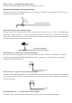
START
MOTOR
85
86
87a
30
RELAY
LOCK
ORANGE ARMING
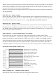
H1/1 & H1/2 Red wire - +12V Power input.
Remove the two 20A fuses prior to connecting these wires and do not replace them until the satellite has been
plugged into the control module. These wires are the source o the current for all the circuits o the relay satellite
will energize. They must be connected to a high current source. Since the factory supplies (+) 12V to the key
switch that is used to operate the monitor, it is recommended that these wires be connected there.
Note: If the factory supplies two separate (+) 12V feeds to the ignition switch, connect one RED wire of the
satellite to each feed at the switch.
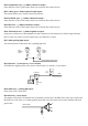
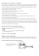
H1/3 Purple wire – Starter output –
START CUT RELAY
(WHEN USED)
IGNITION
SWITCH
OFF
ON
ACC
START
PURPLE WIRE
STARTER
NEUTRAL
SAFETY SWITCH
Careful consideration for the connection of this wire must be made to prevent the vehicle from the starting
while in gear. Understanding the difference between a mechanical and an electrical Neutral Start Switch will
allow you to properly identify the circuit and select the correct installation method. In addition you will realize
why the connection of the safety wire is required for all mechanical switch configuration.
Failure to make this connection properly can result in personal injury and property damage.
In all installations it is the responsibility of the installing technician to test the remote start unit and assure that
the vehicle can not start via RF control in any gear selection other than park or neutral.
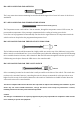
In both mechanical and electrical neutral start switch configurations: the connection of the purple wire will be
made to the low current start solenoid wire of the ignition switch harness. This wire had +12 volts when the
ignition switch is turn to the “Start” position only. This wire will have 0 volts in all other ignition switch
positions.