
Installation Guide
6
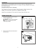
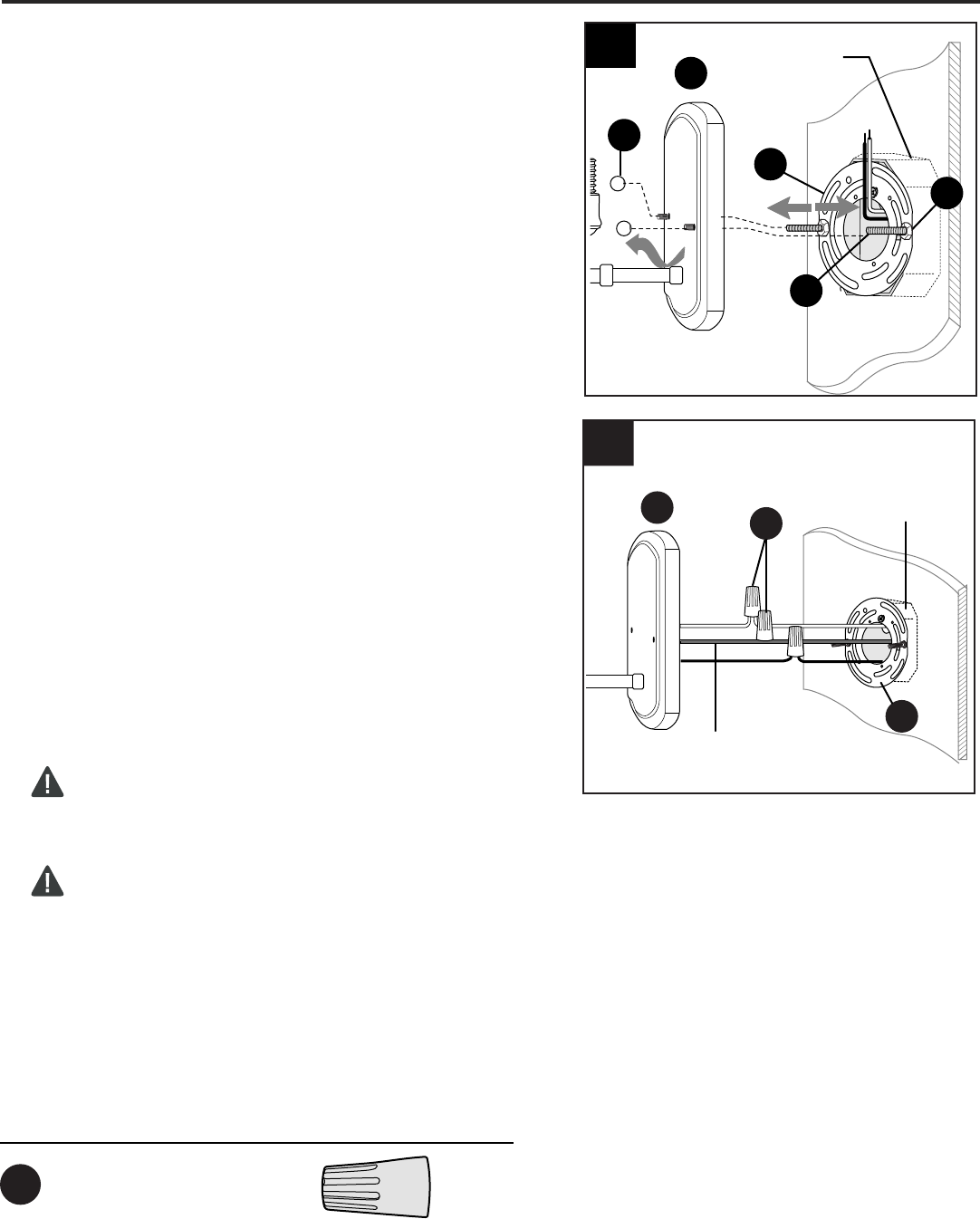
ASSEMBLY INSTRUCTIONS
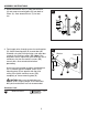
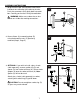
Prepare fixture wires by stripping 3/4 in. of insulation
from wire ends using wire strippers (not included).
Connect WHITE wire from fixture (A) to WHITE wire
from outlet box using existing wire connector or wire
connector (AA). Connect BLACK wire from fixture (A)
to BLACK wire from outlet box using existing wire
connector or wire connector (AA). Connect
BARE/GREEN ground wire from outlet box to BARE
wire from fixture (A) using existing wire connector or
wire connector (AA).
NOTE: Screw wire connectors (AA) on in a clockwise
direction.
WARNING: Never connect BARE/GREEN
ground wire to WHITE or BLACK power supply
wires.
WARNING: To reduce the risk of fire, electrical
shock or personal injury, wire connectors provided
with this light fixture are designed to accept only one
12-gauge house wire and two lead wires from the
light fixture. If your house wire is larger than
12-gauge or there is more than one house wire to
connect to the corresponding fixture lead wires,
consult an electrician for the proper size wire
connectors to use.
6.
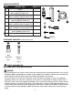
x 3
Hardware Used
Wire Connector
AA
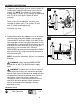
Temporarily place fixture (A) over mounting plate (B)
to determine amount of adjustment necessary for
screws (E). NOTE: The screws (E) should come
through holes in fixture (A) just enough so decorative
nuts (C) will fit flush against fixture (A) when
mounted.
Once screws (E) are adjusted, use pliers (not
included) to tighten nuts (F) on screws (E) until
nuts (F) touch mounting plate (B).
Set fixture (A) aside.
5.
5
Outlet Box
A
F
B
E
C
BARE/GREEN
WHITE
WHITE
BLACK
Outlet
Box
6
A
B
AA