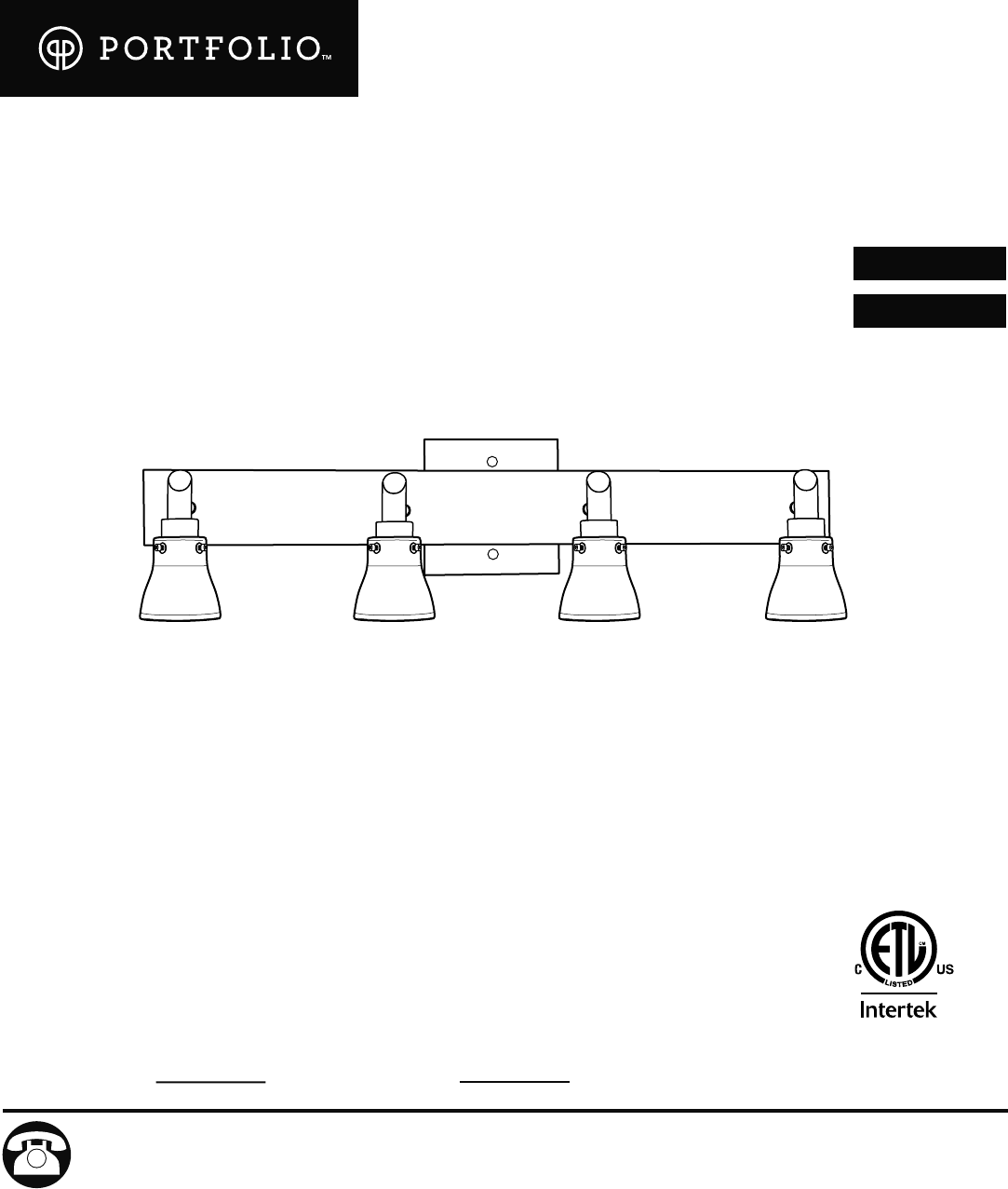
ITEM #0008025 0037316 4-LIGHT VANITY BAR PORTFOLIO® and PORTFOLIO & DesignTM are trademarks or registered trademarks of LF, LLC. All rights reserved. MODEL #VB70BNK-4 VB70-4ORB Français p. 10 Español p. 19 3187807 ATTACH YOUR RECEIPT HERE Serial Number APPROVED FOR USE IN DAMP LOCATIONS Purchase Date Questions, problems, missing parts? Before returning to your retailer, call our customer service department at 1-800-643-0067, 8 a.m. - 6 p.m., EST, Monday - Thursday, 8 a.m. 5 p.m., EST, Friday.
PACKAGE CONTENTS PART A DESCRIPTION Fixture B QUANTITY 1 Thumbscrew (preassembled to fixture (A)) 12 C Glass Shade 4 D Mounting Plate 1 E Decorative Nut (preassembled to mounting plate (D)) 2 F Bulb 4 A B C E D F HARDWARE CONTENTS (shown actual size) AA Wire Connector Qty. 3 BB Machine Screw Qty. 2 SAFETY INFORMATION READ AND SAVE THESE INSTRUCTIONS.
SAFETY INFORMATION DANGER • DO NOT connect the bare or green insulation fixture ground wire to the black (HOT) current-carrying wire or the white (NEUTRAL) house wire. Connection of the bare or green fixture ground wire to the black or white house wires may cause metal parts of the fixture to carry electrical G currents. Under this condition anyone coming in contact with the fixture will receive electrical shock, which could cause serious injury or death.
PREPARATION Before beginning assembly of product, make sure all parts are present. Compare parts with package contents list and hardware contents list. If any part is missing or damaged, do not attempt to assemble the product.
ASSEMBLY INSTRUCTIONS 3. Attach mounting plate (D) to outlet box (not included) using existing washers and outlet box screws or the machine screws (BB). NOTE: If the outlet box screws required for your outlet box are of a different size than the machine screws (BB), consult a licensed electrician before proceeding. 3 Washer D BB Use a level (not included) to adjust mounting plate (D) so fixture screws preassembled to mounting plate (D) are perpendicular to floor and ceiling.
ASSEMBLY INSTRUCTIONS 5. Unwrap BARE fixture wire from BLACK and WHITE fixture wires. Prepare wires by stripping 3/4 in. of insulation from wire ends using wire strippers (not included). NOTE: Fixture (A) can be installed with the sockets facing either up or down. Connect WHITE wire from fixture (A) to WHITE wire from outlet box using existing wire connector or wire connector (AA). Connect BLACK wire from fixture (A) to BLACK wire from outlet box using existing wire connector or wire connector (AA).
ASSEMBLY INSTRUCTIONS 6. Wrap electrical tape (not included) around each individual wire connector (AA) down to the wire. Push wire connectors (AA) gently back into outlet box. Carefully push excess wiring into outlet box. 6 AA AA WARNING: Make sure no bare wire or wire strands are visible after making connections. AA 7. Align holes in fixture (A) with fixture screws on mounting plate (D) and push fixture (A) toward wall.
ASSEMBLY INSTRUCTIONS 9. Remove thumbscrews (B) from socket covers on fixture (A). Align holes in glass shades (C) with holes in socket covers and secure glass shades (C) with thumbscrews (B) previously removed. CAUTION: Do not overtighten thumbscrews (B) as glass may crack or break. 9 Socket Cover A B B C 10. Restore power and test fixture (A). 10 If lights do not function, please refer to TROUBLESHOOTING on the next page.
CARE AND MAINTENANCE • Shut off main power supply. Wipe fixture with soft, damp cloth. Use window cleaner to clean glass. Do not use an abrasive cleaner on glass or fixture. • Bulb Replacement: Use only 50-watt max. halogen bulbs. TROUBLESHOOTING WARNING: Before beginning work, shut off the power supply to avoid electrical shock. PROBLEM Bulb(s) will not light. POSSIBLE CAUSE 1. Bulb(s) is/are burned out. 2. Power is OFF. 3. Faulty connection. CORRECTIVE ACTION 1. Replace light bulb(s). 2.