
Installation Guide


14
ADJUSTMENTS INSTRUCTIONS
NOTE: All the adjustments for the operation of the
drill press have been completed at the factory. Due to
normal wear and use, some occasional readjustments
may be necessary.
To avoid injury from an accidental start, ALWAYS make
sure the switch is in the “OFF” position, the switch key
is removed, and the plug is not connected to the power
source outlet before making adjustments.
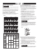
BEVEL DRILLING (FIG. K)
NOTE: A bevel scale has been included to measure
approximate bevel angles. If precision is necessary,
a square or other measuring tool should be used to
position the table. To use the bevel scale (6).
To prevent personal injury, always disconnect the plug
from the power source when making any adjustments.
1. TIGHTEN the nut (4) on the locking pin using wrench
clockwise to RELEASE it from the table support.
2. Loosen the large hex head table bevel locking bolt (5)
using adjustable wrench.
3. Tilt the table, aligning the desired angle measurement
to the zero line opposite the scale (6).
4. Tighten the table bevel locking bolt (5).
5. To return the table to its original position, loosen the
table bevel locking bolt (5). Return the table to the 0°
position.
WARNING
!
WARNING
!
INSTALLING THE BULB (FIG. J)
NOTE: Bulb is not included.
1. Install a light bulb (1) (no larger than 40 watt) into the
socket.
●
For your own safety, never connect plug to
power source outlet until all assembly steps are
complete and you have read and understood the
safety and operating instructions.
●
To prevent injury resulting from heat of the light
bulb. Never touch the light bulb.
●
To prevent electric shock. Never touch the bulb
socket when the plug from the power source is
connected.
Fig. J
WARNING
!
1
ON/OFF SWITCH
6. Return nut (4) on locking pin. Gently tap locking
pin until it is seated in the mating hole of the table
bracket. Hand tighten nut (4).
NOTE: The table support bracket has been removed
from the illustration for clarity.
Fig. K
SPINDLE / QUILL (FIG. L-1)
Rotate the feed handles counterclockwise to lower
spindle to its lowest position. Hold the chuck and move
it front to back. If there is excessive play, proceed with
the following adjustments:
1. Loosen the lock nut (1) located on the left side of the
drill press, using a 14 mm wrench.
2. Turn the screw (2) clockwise to eliminate the play,
using a slotted screwdriver, but without obstructing
the upward movement of the the spindle. (A little play
in the spindle is normal.)
3. Tighten the lock nut (1).
Fig. L-1
QUILL RETURN SPRING (FIG. L-2)
The quill return spring may need adjustment if the
tension causes the quill to return too rapidly or too
slowly.
1. Remove the cap (3), loosen the hex nut (4) and then
remove the hub assembly (7).
2. Lower the table for additional clearance.
3. Place a screwdriver in the lower front notch (8) of he
spring cap (9). Hold it in place while loosening and
removing only the lock nut (6).
4. With the screwdriver still engaged in the notch,
loosen the inner nut (10) just until the notch (11)
disengages from the boss (12) on the drill press
head.
6
5
4
1
2