
User's Manual

TES-63 Source
User manual – version 06/2021
Page 16/46
Polygon Physics SAS au capital social de 72 000 euros - 19, rue de Sassenage - 38600 Fontaine
SIREN 799 584 453 RCS Grenoble - TVA intracommunautaire FR 19 799584453 - APE 2899B
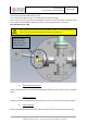
b) Mounting and connecting the gas valve
The gas valve comes with two DN16 iso KF flanges: one for the gas supply line, one for the gas input
on source flange. Make sure the gas valve is mounted on the source flange in the correct orientation
(bottom flange of the valve connected to the source flange).
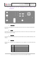
Connect the gas valve cable on the back panel of the control rack with the provided D-Sub 15/ DIN 5
cable and fasten it.
Avoid any dust/scratch/fiber on the vacuum seal surfaces.
Perform a leak check of the gas lines to ensure proper gas inlet purity
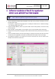
4.3 Installation of the rack and connections
a) Ventilation
CAUTION
It is recommended to have at least 20cm clearance on the back panel, and 5cm
clearance on the top of the control rack.
It is required to install an additional cooling system if ambient air temperature is above
40°C.
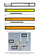
b) Orientation of the rack
The rack must be positioned horizontally. The hole-plate is the air intake and must be on top.
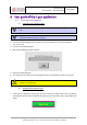
c) Connection to the grid
Make sure the power switch on the control rack is off before using the provided EC22 standard cable
to connect to the grid.
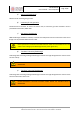
Install a ground strap (not included) between the threaded rod "Ground" and the earth electrode of
the building to properly ground the control rack.
WARNING
Before connecting to the grid, check that all the cover plates are fastened, the ground
connections are made, and that there is proper ventilation.
d) UHF power connection
The transmission of the UHF power between the generator in the control rack and the source is