
User's Manual

TES-63 Source
User manual – version 06/2021
Page 12/46
Polygon Physics SAS au capital social de 72 000 euros - 19, rue de Sassenage - 38600 Fontaine
SIREN 799 584 453 RCS Grenoble - TVA intracommunautaire FR 19 799584453 - APE 2899B
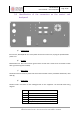
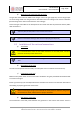
6
Relay, signal to switch
7
Relay, normally open state
8
Ground
9
+24V, 1A max
Connect the reading of a pressure gauge controller (not included) to pin 3.
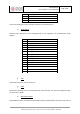
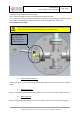
e) Data Enter 2
Female D-Sub 9 connector for the reading/control of user equipment. The terminal block wiring
diagram:
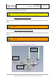
f) USB
Female USB connector, only for factory use.
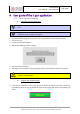
g) RJ45
Ethernet port allowing access to shared folder with microcontroller. The data and configuration files
are stored in this folder.
h) Microwave Power
Female SMA connector, to transfer the Ultra High Frequency power between the control rack and the
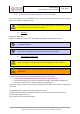
Pin
DATA ENTER 2
1
Analog output 1, 0-10V, 16 bits
2
Analog output 2, 0-10V, 16 bits
3
Ground
4
Analog input 2, 0-10V, 24bits
5
Analog input 3, 0-10V, 24bits
6
Analog input 4, 0-10V, 24bits
7
Analog input 5, 0-10V, 24bits
8
Analog input 6, 0-10V, 24bits
9
Analog input 7, 0-10V, 24bits
10
Analog input 8, 0-10V, 24bits
11
Analog input 9, 0-10V, 24bits
12
Ground
13
Ground
14
+24V, 1A max
15
+5V, 1A max