
Network Router - Wireless Network Device User Manual
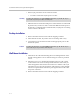
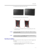

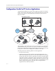
Table Of Contents
- Introduction
- Getting Started
- Configuring the V2IU 4350
- Configuration Guide For IP Centrex Applications
- Configuration Guide For Station Side IP PBX Applications
- Configuration Guide For Trunk Side IP PBX Applications
- Configuration Guide For Hosted Video Applications
- Configuration Guide For Enterprise Video Applications
- System Configuration
- Read-only User
- Subinterfaces
- ToS Byte Setting
- H.323 Configuration
- Forwarding Rules
- Peering Proxy
- Clients List Lock
- H.323 Activity Monitor
- VoIP Configuration
- Data Networking Configuration
- Traffic Management Configuration
- System Diagnostics
- Saving and Restoring the V2IU 4350 Configuration
- Upgrading the V2IU 4350
- Appendix
- Regulatory Notices
Getting Started
2 - 3
4. Mount the 4350 on the wall as shown below.
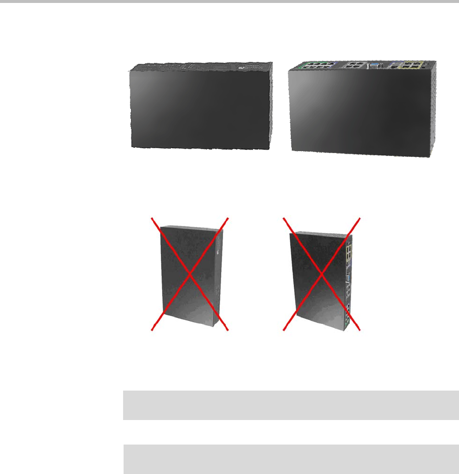
Do not mount the 4350 on the wall as shown below.
1. Connect the power and network cables to the appropriate ports on the
back of the system.
Rack-Mount Installation
You can mount the 4350 in a shelf by using the rack-mount kit supplied with
the product.
1. Attach the ear mounts to both sides of 4350 with the screws.
2. Attach the 4350 with the ear mounts to the shelf by screwing the ear
mounts to the shelf with screws.
Warning
Secure the power supply using a fastener or nearby shelf so that it does not hang
from the power connector.
Caution
To reduce the risk of fire, use only 26 AWG or larger wire (e.g. 24, 22, 20, etc.) to
connect the T1 port on your unit to an RJ-45 jack.