SpectraLink 8000 SVP Server SVP100 Administration Guide for SRP January 2008 Edition 1725-36032-001 Version F
SpectraLink 8000 SVP Server: Administration Guide for SRP Trademark Information Notice Polycom® and the logo designs SpectraLink® LinkPlus Link NetLink SVP Are trademarks and registered trademarks of Polycom, Inc. in the United States of America and various countries. All other trademarks used herein are the property of their respective owners. Polycom, Inc. has prepared this document for use by Polycom personnel and customers.
About this Guide This document explains how to configure and maintain one or more SpectraLink 8000 SVP Servers within the SpectraLink 8000 Telephony Gateway system.
SpectraLink 8000 SVP Server: Administration Guide for SRP Customer Support Hotline Polycom wants you to have a successful installation. If you have questions please contact the Customer Support Hotline at (800) 775-5330. The hotline is open Monday through Friday, 6 a.m. to 6 p.m. Mountain time. Icons and Conventions This manual uses the following icons and conventions. Caution! Follow these instructions carefully to avoid danger. Note these instructions carefully.
Contents 0 About this Guide ......................................................................3 Polycom Model Numbers..................................................................3 Related Documents.............................................................................3 Customer Support Hotline ................................................................4 Icons and Conventions.......................................................................4 1 SpectraLink 8000 SVP Server Overview ..
SpectraLink 8000 SVP Server: Administration Guide for SRP Network Configuration....................................................................21 SendAll .........................................................................................22 SVP Server Configuration................................................................24 Change Password..............................................................................27 4 Swapping/Adding/Deleting SVP Servers................................
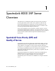
1 SpectraLink 8000 SVP Server Overview The SVP Server is an Ethernet LAN device that works with APs to provide QoS on the wireless LAN. Voice packets to and from the SpectraLink 8000 Wireless Telephones are intercepted by the SVP Server and encapsulated for prioritization as they are routed to and from the SpectraLink 8000 Telephony Gateway. One or more SVP Servers are required in systems with five or more SpectraLink 8000 Telephony Gateways.
SpectraLink 8000 SVP Server: Administration Guide for SRP Multiple SVP Servers Multiple SVP Server environments are those which have more than one SVP Server. Up to 16 SVP Servers may be installed in any one subnet. The Timing Function In the SpectraLink Gateway environment, SVP Servers provide the "timing" function for active calls. In multiple SVP Server environments, the active calls are distributed across the SVP Servers. The number of active SVP Servers is determined dynamically.
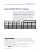
SpectraLink 8000 SVP Server Overview SpectraLink 8000 SVP Server Capacity The table below shows the capacity of SpectraLink 8000 Telephony Gateways in a multiple SVP Server environment. The table shows the total possible calls at 100% active calls. However, since it is unlikely that all handsets will be in use at the same time, the table then analyzes the number of handsets that could be installed in any given system where 15%, 25% or 50% of the handsets are in active calls at any one time.
SpectraLink 8000 SVP Server: Administration Guide for SRP Notes on System Configuration Wireless telephones cannot roam with uninterrupted service between subnets unless specific LAN components are present. Certain AP/Ethernet switch combinations establish a layer-2 tunnel across subnets that enables the handsets to roam.
SpectraLink 8000 SVP Server Overview System Diagram The following diagram shows one SpectraLink 8000 SVP Server residing on a network with five SpectraLink 8000 Telephony Gateways, wireless LAN APs, and Ethernet switch: Admin computer access point SpectraLink 8000 SVP Server Ethernet Switch SpectraLink Wireless Telephones access point SpectraLink 8000 Telephony Gateway optional SpectraLink 8000 Telephony Gateway Wireless POS SpectraLink 8000 Telephony Gateway SpectraLink 8000 Telephony Gateway Sp
SpectraLink 8000 SVP Server: Administration Guide for SRP System Components SpectraLink e340/h340/i640 and 8020/8030 Wireless Telephones Employees can carry wireless telephones to make and receive calls as they move throughout the building. The wireless telephones are to be used on-premises; they are not cellular or satellite phones. They are connected to the facility's existing telephone system and to the SpectraLink 8000 Telephony Gateway.
SpectraLink 8000 SVP Server Overview wireless data devices. Contact Polycom, or a certified Polycom distributor, for specific information about your facility’s needs. The SpectraLink system must connect to APs that utilize SVP. Contact Polycom, or a certified Polycom distributor, to verify that your AP and its software version are supported. Ethernet switch Ethernet switches interconnect multiple network devices, including APs and SpectraLink 8000 Telephony Gateways.
SpectraLink 8000 SVP Server: Administration Guide for SRP The Front Panel of the SVP Server The SVP Server’s front panel contains ports to connect to power, the LAN, and to an administrative computer via an RS-232 port. Status LEDs supply information about the SVP Server’s functioning. 1 L N K O K A C T C O L NETWORK E R R O R 2 3 4 5 PWR Status RS-232 RS-232 port: male DB-9 connector (DTE) used for RS-232 connection to a terminal, terminal emulator, or modem for system administration.
2 Installing the Spectralink 8000 SVP Server As shown in the system diagram the SVP Server is connected to the Ethernet switch. The specifications covered here allow for great flexibility in physical placement of the components within stated guidelines. Required Materials The following equipment must be provided by the customer. Power Outlet – AC adapter provided by Polycom Backboard space – The SVP Server is designed to be wallmounted to 3/4" plywood securely screwed to the wall.
SpectraLink 8000 SVP Server: Administration Guide for SRP • A maximum distance of 325 feet (100 meters) from the Ethernet switch. Install the SVP Server The SVP Server may be mounted on a rack or to a wall. Mount the SVP Server on a rack The rack mount kit is designed for mounting equipment in a standard 19” rack and should contain the following equipment: Mounting plates– two for each SVP Server to be mounted. Screws– four rack mount screws for each SVP Server to be mounted.
Installing the SpectraLink 8000 SVP Server Connect SVP Server to LAN Using a Cat. 5 cable, connect the NETWORK port on the SVP Server to the connecting port on the Ethernet switch. Connect power 1. Connect the power plug from the AC adapter to the jack labeled PWR on the SVP Server. Use only the provided Class II AC Adapter with output 24VDC, 1A. 2. Plug the AC adapter into an 110VAC outlet to apply power to the SVP Server. 3.
3 Configuring the SpectraLink 8000 SVP Server During initial setup of the SVP Server the IP address is established and the maximum number of active calls per AP is set. Optionally, you may enter a hostname and a location for software updates via TFTP. Connecting to the SVP Server The initial connection to the SVP Server must be made via a serial connection to establish the SVP Server’s IP address. After the IP address is established, connection to the SVP Server may be done via the network using Telnet.
SpectraLink 8000 SVP Server: Administration Guide for SRP Connecting via telnet Telnet can only be used after the SVP Server’s IP address is configured. The Telnet method of connection is used for routine maintenance of the SpectraLink Server for both local and remote administration, depending on your network. To connect via Telnet, run a Telnet session to the IP address of the SVP Server. Once you connect and log in, the NetLink SVP-II System menu displays.
Configuring the SpectraLink 8000 SVP Server Network Configuration The IP address and other network settings are established via the Network Configuration screen. This is also where you may optionally establish a hostname and enter the IP address of the location of any software updates you may obtain from Polycom. See Chapter 5 Software Maintenance for more information about installing software updates via TFTP. Scroll to Network Configuration and select by pressing Enter.
SpectraLink 8000 SVP Server: Administration Guide for SRP SendAll In a system with multiple SVP Servers, the SendAll option is provided to speed configuration and to ensure identical settings. The S=SendAll option allows you to send that configuration parameter to every SVP Server on the LAN. SendAll can only be used after the IP address is established on EACH SVP Server via the serial connection.
Configuring the SpectraLink 8000 SVP Server Subnet Mask The network administrator must define the subnet mask. Default Gateway The IP address of a router on the local subnet. SVP-II TFTP Download Master This entry indicates the source of software updates for the SVP Server. See Chapter 5 Software Maintenance for more information. Valid source location entries are: • NONE: disables. • IP Address: The IP address of a network TFTP server that will be used to transfer software updates to the SVP Server.
SpectraLink 8000 SVP Server: Administration Guide for SRP Syslog Server Logging can be set to Syslog or NONE. If Syslog is set, a message is sent to the syslog server when an alarm is triggered. Disable Telnet service Prevents Telnet access into the SVP Server. Reset the SVP Server for the change to take effect. Upon reset the Telnet protocol server is not started. The SVP Server must be reset in order to set the configuration options.
Configuring the SpectraLink 8000 SVP Server The SVP Server will automatically lock for maintenance if the IP address is changed. When this Maintenance Lock occurs, the SVP Server must be reset upon exit. All active calls are terminated during a reset. SVP-II Mode Set to NetLink when using a SpectraLink 8000 Telephony Gateway. Ethernet link The SVP Server will auto-negotiate unless there is a need to specify a link speed. System Locked This option is used to take the system down for maintenance.
SpectraLink 8000 SVP Server: Administration Guide for SRP that the administrator cannot change this option. It is automatically set by the system. Reset the system at exit to clear Maintenance Lock. Inactivity Timeout (min) Set the number of minutes the administrative module can be left unattended before the system closes it. This number can be from 1 to 100. If it is set to zero (0), the administrative module will not close due to inactivity.
Configuring the SpectraLink 8000 SVP Server RTP traffic is the audio traffic to the PBX. It requires voice quality. PBX traffic is not audio to the PBX. Inter-SVP2 traffic is the information-passing protocol that SVP Servers use to communicate with each other. The final DSCP tag of traffic for packets in each of the above Traffic Classes is governed by the logic below when SVP is used in an SRP environment: • If in-call and WT (In call) value is not Default then the configured value is used.
SpectraLink 8000 SVP Server: Administration Guide for SRP 1. Select Change Password from the main menu. A screen similar to the following will appear: 2. Enter the information and either select Set Password or press the S key to set the new password. If you forget a password, call Polycom Customer Service for assistance. 28 PN: 1725-36032-001_F.
4 Swapping/Adding/Deleting SVP Servers Whenever an SVP Server is removed from the system, wireless telephones that are using the SVP Server will be affected. If the removal of the SVP Server is intentional, the administrator should lock and idle the system prior to removing an SVP Server. Whenever an SVP Server is added to the system, the change is seamless and does not affect wireless telephone calling functionality.
5 Software Maintenance The SVP Server uses proprietary software programs written and maintained by Polycom Corporation. The software versions that are running on the system components can be displayed via the System Status screen. You may obtain information about software updates from Polycom or its authorized dealer. At startup the SVP Server uses TFTP to check the software version it is running against the version in the TFTP location.
6 Troubleshooting via System Status Menu Information about system alarms, and network status displays on various screens accessed through the System Status Menu screen, which is opened from the main menu of the SVP Server. See the previous sections for directions on how to connect to the SVP Server and navigate to the System Status Menu. Error Status —displays alarm and error message information. Network Status —displays information about the Ethernet network to which the SVP Server is connected.
SpectraLink 8000 SVP Server: Administration Guide for SRP system function and to troubleshoot areas that may be experiencing trouble. Error Status The Error Status screen displays any alarms that indicate some system malfunction. Some of these alarms are easily remedied and others require a call to Polycom’s Customer Support Department. From the System Status Menu, select Error Status. The screen displays active alarms on the SVP Server.
Troubleshooting via System Status Menu From the System Status Menu, select Network Status. The screen displays information about the Ethernet network. This information can help troubleshoot network problems. A sample screen is displayed here. Ethernet Address – MAC address of the SVP Server (hexadecimal). System Uptime – the number of days, hours and minutes since the SVP Server was last reset. Net – the type of connection to the Ethernet switch currently utilized.
SpectraLink 8000 SVP Server: Administration Guide for SRP fifo – overrun occurred during reception alignment – nonoctet-aligned packets (number of bits NOT divisible by eight) multicast – packets received with a broadcast or multicast destination address TX – Ethernet statistics concerning the transmitted packets during System Uptime.
Troubleshooting via System Status Menu This screen also displays the model type. From the System Status Menu, select Software Version. A sample screen is displayed here. Note that the software versions on your system may be different from the versions displayed in the above sample screen. The table below shows the description, major version numbers, and filenames of the files that are provided when downloading updates. Table of contents Major Version Number 173 svp100.
Safety Notices WARNING: Changes or modifications to this equipment not approved by SpectraLink Corporation may cause this equipment to not comply with part 15 of the FCC rules and void the user’s authority to operate this equipment. WARNING: SpectraLink products contain no user-serviceable parts inside. Refer servicing to qualified service personnel. IMPORTANT SAFETY INFORMATION Follow these general precautions while installing telephone equipment: PN: 1725-36032-001_F.
Index A P Access Point, description .....................................13 Alarms ....................................................................34 Power......................................................................15 C Configuration Initial setup .......................................................22 Customer Support Hotline ....................................4 D Download master .................................................23 Downloading Software Updates ........................