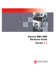
Polycom RMX 2000 Hardware Guide Version 1.
Copyright © 2007 Polycom, Inc. All Rights Reserved Catalog No. DOC2160A Version 1.1 Proprietary and Confidential The information contained herein is the sole intellectual property of Polycom, Inc. No distribution, reproduction or unauthorized use of these materials is permitted without the expressed written consent of Polycom, Inc. Information contained herein is subject to change without notice and does not represent commitment of any type on the part of Polycom, Inc.
Regulatory Notices United States Federal Communication Commission (FCC) CE Mark R&TTE Directive Part 15: Class A Statement. This equipment has been tested and found to comply with the limits for a Class A digital device, pursuant to Part 15 of the FCC Rules. Test limits are designed to provide reasonable protection against harmful interference when the equipment is operated in a commercial environment.
Regulatory Notices Chinese Communication Certificate
Polycom RMX 2000 Hardware Guide Table of Contents Hardware Description . . . . . . . . . . . . . . . . . . . . . . . . . . 1-1 Main Features .......................................................................................... 1-1 RMX 2000 Specifications ....................................................................... 1-2 Site Requirements ................................................................................... 1-3 Safety Requirements .................................................
Table of Contents ii
1 Hardware Description This Hardware Guide provides information on the RMX 2000 and its components. This system utilizes a modular “universal slot” platform, whose components are designed for high performance, capacity and reliance.
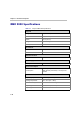
Chapter 1- Hardware Description RMX 2000 Specifications Table 1-1 Polycom RMX 2000 Specifications Physical Height 3U (13.28 cm.) Width 19” (48.26 cm.) Depth 15.74” (40 cm.) Weight Up to 16.5 Kg. Free space above MCU 3” standard installation IP Protocols Audio G.711, G.722, G.722.1, G.729A, G.723.1, Siren14 Video H.263, H.264 Network Interfaces IP H.
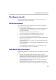
Polycom RMX 2000 Hardware Guide Site Requirements This section describes the requirements your site must meet for safe installation and operation of the system. Safety Requirements For your protection, please read these safety instructions completely before operating the equipment. • Look carefully for potential hazards in your work area: moist floors, ungrounded power cables, frayed power cords, missing safety grounds and so forth. • Locate the main circuit breaker within the room.
Chapter 1- Hardware Description • In a single rack installation, stabilizers should be attached to the rack. • In multiple rack installations, the racks should be coupled together. • Always make sure the rack is stable before extending a component from the rack. • You should extend only one component at a time - extending two or more simultaneously may cause the rack to become unstable. • Before you install the rails, determine the placement of each component in the rack.
Polycom RMX 2000 Hardware Guide RMX 2000 Components On the RMX 2000 modules are located on both the front and rear of the MCU as listed in Table 1-2, "Polycom RMX 2000 Component Description". For more information see the descriptions of the "RMX 2000 Front Panel” on page 1-5 and "RMX 2000 Rear Panel” on page 1-7. RMX 2000 Front Panel Figure 1-1 shows the front panel of the RMX 2000. The front panel provides access to the RMX 2000 main CNTL modules, MPM modules, Power Supply drawer, Status LEDs, and Fans.
Chapter 1- Hardware Description Table 1-2 Polycom RMX 2000 Component Description Component Description CPU (CNTL) Module The CPU Module controls and manages the RMX 2000. The CPU Module has an ComExpress Pentium-M 1.4 GHz processor, a 40GB hard disk drive, 1GB Compact Flash and 512MB of DDR RAM. The Operating System is Linux. Power Supply Drawer The Power Supply Module is housed in a drawer and located below the MPM Modules.
Polycom RMX 2000 Hardware Guide RMX 2000 Rear Panel The RMX 2000 rear panel contains the RTM IP board. In addition, the rear panel houses the main power switch, AC inlet, a circuit breaker, and additional communications ports. RTM IP The RTM IP board provides system shelf management based on the ATCA standard. It controls and monitors fans on the system and regulates power supply. This board contains an Ethernet Switch managing the network of the system and routing traffic.
Chapter 1- Hardware Description The following items appear on the RMX 2000 rear panel: Table 1-3 1-8 RMX 2000 Rear Panel - RTM IP Component Description Function Name Description LAN 1 NA - Disconnected. LAN 2 Used for the Network connection. LAN 3 For Remote Access only using the Permanent Management Network. For more information, see the RMX 2000 Administrator’s Guide, Appendix F: "Permanent Management Network” on page F-1. 10/100 ShMC NA - For debugging purposes only.
Polycom RMX 2000 Hardware Guide Cables Connected to the RTM IP Board All external connectors are located on the rear panel.
Chapter 1- Hardware Description RMX 2000 LEDs The RMX includes LEDs located on the front panel and rear panel. In the front panel, the LEDs reflect the state of the module. The LEDs on the rear panel indicate the state of the external connections and the status of the RTM IP board RMX 2000 Front Panel LEDs The following items appear on the RMX 2000 front panel: Table 1-4 RMX 2000 Front Panel LED’s Function Name LED ID LED Color Description Green OK. Red Warning - Fan failure. Green OK.
Polycom RMX 2000 Hardware Guide Table 1-4 RMX 2000 Front Panel LED’s (Continued) Function Name LED ID LED Color Description MPM ERR Red ON - Major error on board. RDY Green ON - The board has completed startup successfully. ACT Amber ON - At least one participant is connected to a conference. HS Blue ON - The card can be removed safely once the CPU ejector mechanism is activated.
Chapter 1- Hardware Description Table 1-5 RMX 2000 Rear Panel LEDs (Continued) Function Name SLOT (1-4) LEDs ShMC LEDs LED Name LED Color Description LNK (1-4) Green Lit with active network connection, flickers with Packet activity. 1Gb (1-4) Amber Lit when 1Gb connection online, flickers with Packet activity. ERR Red ON - Major error on RTM board. ACT Red ON - Packet flow to and from the MCU chassis. RDY Green ON - RTM IP board has successfully completed startup.
Polycom RMX 2000 Hardware Guide Component Replacement The RMX 2000 is designed with ease of maintenance in mind. Most components are swappable and are accessible directly via the front panel or the rear panel. The following components can be replaced when they are faulty: • CPU (CNTL) Module • Multi Processor Module (MPM) Board(s) • Power Supply Module • Fan Drawer RTM IP Board Warning! • All maintenance tasks are to be performed by qualified, authorized personnel.
Chapter 1- Hardware Description Replacing the CPU (CNTL) Module The CPU module is the management system of the RMX 2000. Use the following procedure to replace a CPU (CNTL) Module: 1-14 1 Ensure that power switch to the RMX 2000 is turned OFF (O). 2 Unscrew the screws on the front panel of the RMX 2000 that secure the CPU (CNTL) Module. 3 Use the metal ejectors to pull the CPU (CNTL) Module out of its slot in the Backplane. 4 Carefully slide the CPU (CNTL) Module out through the front panel.
Polycom RMX 2000 Hardware Guide Replacing a Functional MPM Module Use the following procedure to replace a faulty MPM Module types F or H: 1 Ensure that power switch to the RMX is turned OFF (O). 2 Unscrew the screws on the front panel of the RMX that secure the MPM Module. 3 Use the metal ejectors to pull the MPM Module out of its slot in the Backplane. 4 Carefully slide the MPM Module out through the front panel. 5 Slide in the replacement MPM Module.
Chapter 1- Hardware Description Replacing the Power Supply Drawer A single supply unit powers the RMX 2000. Use the following procedure to replace a Power Supply: 1-16 1 Ensure that power switch to the RMX 2000 is turned OFF (O). 2 Unscrew the screws on the front panel of the RMX 2000 that secure the Power Supply. 3 Use the metal ejectors to pull the Power Supply Module out of its slot in the Backplane. 4 Carefully slide the Power Supply Module out through the front panel.
Polycom RMX 2000 Hardware Guide Replacing the Fan Drawer Three fans are mounted in the Fan Drawer, where the airflow is from right to left. Should one of these fans fail as indicated by a Fan LED, you are required to replace the fan drawer. 1 Unscrew the screws on the front panel of the RMX 2000 that secure the Fan Drawer. 2 Use the metal ejectors to pull the Fan Drawer out of its slot in the Backplane. 3 Carefully slide the Fan Drawer out through the front panel.
Chapter 1- Hardware Description Replacing the RTM IP Board The RTM IP board on the rear of the RMX 2000 provides connectivity to all the MCU modules. Use the following procedure to replace the RTM IP board: 1-18 1 Ensure that power switch to the RMX 2000 is turned OFF (O). 2 Unscrew the screws on the rear panel of the RMX 2000 that secure the RTM IP board. 3 Use the metal ejectors to pull the RTM IP board out of its slot in the Backplane.