Installed Voice Business Group RS-232 Command Set: Vortex EF2211 Programming Guide Copyright © 2003 Polycom, Inc. Polycom and the Polycom logo are registered trademarks of Polycom, Inc. ASPI, Vortex, VS4000, Viewstation, and iPower are registered trademarks of Polycom, Inc.
Vortex EF2211 Programming Guide Table of Contents 1. Introduction 2. RS-232 Hardware 3. Programming Tips 3.1. Initialization 3.2. Wildcard Characters 3.3. Using Acknowledgements 3.4. Macros and Presets 4. Command Structure 4.1. Device Type 4.2. Device ID 4.3. Command Name 4.4. Command Data 4.5. Command Terminator 4.6. Examples 5. Status Messages 6. Command Types 6.1. Boolean Commands 6.2. Integer Commands 6.3. Channel Commands 6.4. Matrix Commands 6.5. Miscellaneous Commands 7. Command List 8.
8.14. 8.15. 8.16. 8.17. 8.18. 8.19. 8.20. 8.21. 8.22. 8.23. 8.24. 8.25. 8.26. 8.27. 8.28. 8.29. 8.30. 8.31. 8.32. 8.33. 8.34. 8.35. 8.36. 8.37. 8.38. 8.39. 8.40. 8.41. 8.42. 8.43. 8.44. 8.45. 8.46. 8.47. 8.48. 8.49. 8.50. 8.51. 8.52. 8.53. 8.54. 8.55. 8.56. 8.57. 8.58.
8.59. GAINO -- Set Output Gain 8.60. GAINP -- Set Phone Output Gain 8.61. GAINSIT -- Set From Phone User Tone Gain 8.62. GAINSOT -- Set To Phone User Tone Gain 8.63. GATE -- Query Gating Status Information 8.64. GATEEN -- Enable Automatic Gating Messages 8.65. GMUTEO -- Mute All Outputs 8.66. ID -- Set Device ID 8.67. LABEL -- Set or Query one of the Device Labels 8.68. LAGC -- Enable or Disable Line Input Automatic Gain Control 8.69. LAGCLINKAB -- Enable or Disable Stereo AGC Linking on Inputs A and B 8.
8.104. 8.105. 8.106. 8.107. 8.108. 8.109. 8.110. 8.111. 8.112. 8.113. 8.114. 8.115. 8.116. 8.117. 8.118. 8.119. 8.120. 8.121. 8.122. 8.123. 8.124. 8.125. 8.126. 8.127. 8.128. 8.129. 8.130. 8.131. 8.132. 8.133. 8.134. 8.135. 8.136. 8.137. 8.138. 8.139. 8.140. 8.141. 8.142. 8.143. 8.144. 8.145. 8.146. 8.147. 8.148.
8.149. 8.150. 8.151. 8.152. 8.153. 8.154. 8.155. SSTEXT -- Set Text to be Displayed by Screen Saver SWRESET -- Perform Soft Reset of System SWVER -- Query Software Version TONEE -- Enable or Disable Entry and Exit Tones TONER -- Enable or Disable Ring Tones VTXMODI -- Enable VTX Mode on Specified Inputs VTXMODO -- Enable VTX Mode on Specified Inputs 1. Introduction This document describes the command protocol that is used to communicate with the Vortex EF2211 via its RS-232 port. 2.
3.2. Wildcard Characters The use of the wildcard character, '*', can make programming the host controller much easier. Be careful when using wildcards, however, since they can generate a lot of traffic on the digital bus. 3.3. Using Acknowledgements It is a good idea for the host program or control system to make sure that all connected Vortex devices have acknowledgment mode enabled (see the ACKMOD command).
3.4. Macros and Presets Although macros and presets are similar, there are times when using one is better than the other. Presets store the absolute values of all of the non-global settings of the device. This includes, but is not limited to, input and output gain settings, matrix settings, algorithm settings, parametric EQ settings, and automixer settings. See Section 7 for a list showing all the commands and which are saved to presets.
A single alphanumeric character is used to indicate the device type. The devices in Polycom's EchoFree family have the following device types. Device Device Type EF200 A EF1210 C EF2280 F EF2241 B EF2211 S EF2210 Q EF2201 T Device type '*' can be used to send a command to all device types simultaneously. 4.2. Device ID Two numeric characters are used to indicate the device ID. The Vortex can be configured for device IDs from '00' to '07'.
chosen as the terminator to allow manually typing commands using a simple text terminal. 4.6. Examples In the following examples, Vortex commands are enclosed in single quotes, 'like this'. Also, the terminator character is not explicitly shown, but its presence is implied. Consider the command '***PING'. The device type and ID for this command are wildcards, thus the command will be sent to all devices. The command name in this case is 'PING', and there are no data characters (payload).
6.1. Boolean Commands Boolean commands take one of the three following arguments. ● ● ● '0' indicates that the parameter should be turned off. '1' indicates that the parameter should be turned on. '2' indicates that the parameter should be toggled (i.e., '0' becomes '1' and '1' becomes '0'). Parameters associated with boolean commands can be queried using the '?' character. For example, if input A is muted, and you send ' S04MUTEIA? ', the EF2211 will respond with a status message of ' S04MUTEIA1 '.
respond with a status message of ' S04AGC10 '. An example of an integer channel command is the 'GAINI' command, which adjusts the gain on the input channels. ' S04GAINIA12 ' sets the input gain of channel A to 12 dB. After sending this command, the device will respond with a status message of ' S04GAINIA12 '. A wildcard character ('*') can be used as the channel specifier for many of the channel commands. If this is the case, there are two options for specifying the values for the channels.
Queries using the '?' character are straightforward. For example, ' S04GAINI1? ' might return ' S04GAINI110 ', while ' S04GAINI*? ' might return ' S04GAINI*Äää '. 6.4. Matrix Commands Matrix commands are used for controlling parameters that exist at the crosspoints of the mixing matrices. Typical parameters include gain and mute. Before describing the matrix commands, it is necessary to give a description of the matrices involved.
tied to output 1. Thus the signal routed to output 1 will also be routed to the power amplifier output. This yields a total of four physical outputs. The EF2211 has three analog inputs labeled 1, A, and B. Input 1 is mic/line selectable, and inputs A-B are line level only. Input 1 can also have phantom power enabled and contain channel processing, which includes the following DSP algorithms: Acoustic Echo Cancellation, Noise Cancellation, and AGC.
● ● Inputs: WB0-WB7 (with one invalid) Outputs: WM0-WM2 X Submatrix ● ● Inputs: XB0-XB7 (with one invalid) Outputs: XM0-XM2 Y Submatrix ● ● Inputs: YB0-YB7 (with one invalid) Outputs: YM0-YM2 Z Submatrix ● ● Inputs: ZB0-ZB7 (with one invalid) Outputs: ZM0-ZM2 For the P signal, bus there is a 7 x 2 matrix that allows the user to define up to two mixes of the P signal bus.
It is also possible to use the wildcard character ('*') to specify ranges of crosspoints with the matrix commands. The only restriction is that you can only use a wildcard to specify the input or output, but not both simultaneously. Thus you could specify all the inputs going to a specific output (one column) or the value of an input to all of the outputs (one row), but not the entire matrix. One example of using a wildcard for an integer matrix command would be ' S04MGAINSG,*,0 '.
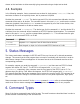
The Storage column contains one of the following values indicating when and where the parameter is stored. ● ● ● "Global" "Preset" "-" = not stored or not applicable Globally stored parameters are not changed when a preset is executed. Only one copy of a global parameter is stored. Global parameters are written to non-volatile memory each time they are changed. Globally stored parameters retain their values when the power is cycled.
AMNOM Preset Set Local Maximum Number of Open Mics for Automixer AMNOMAT Preset Select NOM Attenuation on Each Output AMOFFAT Preset Set Off Attenuation for the Specified Automixer AMPRIOR Preset Set Gating Priority for the Specified Mic AMREFB Preset Set Automixer Reference Bias for the Specified Automixer AMREFE Preset Enable Automixer Reference for Specified Automixer BAUD Global Set Baud Rate for RS-232 Port BLAUTO Preset Enable Automatic BLDATA Messages BLDATA - Request Level
GAINI Preset Set Input Gain GAINO Preset Set Output Gain GAINP Preset Set Phone Output Gain GAINSIT Preset Set From Phone User Tone Gain GAINSOT Preset Set To Phone User Tone Gain GATE - Query Gating Status Information GATEEN Preset Enable Automatic Gating Messages GMUTEO Preset Mute All Outputs ID Global Set Device ID LABEL Global Set or Query one of the Device Labels LAGC Preset Enable or Disable Line Input Automatic Gain Control LAGCLINKAB Preset Enable or Disable Stere
MACROA - Add Command to Current Macro MACROK Global Delete One or All Macros MACROL - List All Commmands in a Macro MACROQ - Execute Macro Quietly MACROS - Start a New Macro MACROW Global Write Macro to Non-Volatile Memory MACROX - Execute Macro METER Preset Select which Signal is Displayed on the Front Panel LED Meter MGAIN Preset Set Crosspoint Gains in Main Matrix or Submatrix MGATE Preset Select Gated or Ungated Microphone Signal in Matrix MIC Preset Enable Microphone Gai
PEQOS Preset Set Slope Parameter for Specified Parametric EQ Output Stage PEQOT Preset Set Type Parameter for Specified Parametric EQ Output Stage PHANTOM Preset Enable Phantom Power on Input 1 PHONE - Take Phone On-Hook or Off-Hook PING - See Which Devices Are Present PRESETK Global Delete One or All Presets PRESETL - List All Commmands in a Preset PRESETP Global Set Which Preset Will Be Activated At Power-Up PRESETQ - Execute a Preset Quietly PRESETW Global Save a Preset PRES
This command sets or queries the status of the auto answer feature. This command is a boolean command. See Section 6.1 for more information on this type of command. This command is saved to non-volatile memory only as part of a preset. The state of this command will be restored after power-up only if a preset is saved and that preset is set to be the power-on preset. Example Description Status Message S01AA1 Enable auto answer mode. S01AA1 S01AA0 Disable auto answer mode.
This command is saved to non-volatile memory only as part of a preset. The state of this command will be restored after power-up only if a preset is saved and that preset is set to be the power-on preset. Example Description Status Message S01AEC11 Enable AEC on input channel 1. S01AEC11 S01AEC10 Disable AEC on input channel 1. S01AEC10 S01AEC12 Toggle AEC state on input channel 1. S01AEC1x , where x is 0 or 1 depending on the current state of the AEC on input channel 1.
channels 1 and T (the telephone input) . Using the wildcard character, '*', to specify the channel with this command is not supported for the EF2211. To set or query the command, the channels must be specified explicitly (e.g., 'S01AGC1?', 'S01AGCT0'). This command is a channel boolean command. See Section 6.3 and Section 6.1 for more information on this type of command. This command is saved to non-volatile memory only as part of a preset.
S01AGCMAXTx where x is a number Query the AGC maximum gain on input between 0 and 15, depending on the current S01AGCMAXT? channel T . setting of the AGC maximum gain on input channel T . 8.7. AGCMIN -- Set Minimum Allowed Mic/Line Input AGC Gain This command sets the minimum gain that the AGC can apply on input channels 1 and T (the telephone input) . For example, if AGCMIN is set to -10, then the AGC for that channel can apply a minimum of -10 dB of gain to the input signal.
This command is saved to non-volatile memory only as part of a preset. The state of this command will be restored after power-up only if a preset is saved and that preset is set to be the power-on preset. Example Description S01AGCRATE13 Set AGC ramp rate on input channel S01AGCRATE13 1 to 3 dB/sec. S01AGCRATET? Query the AGC ramp rate on input channel T . Status Message S01AGCRATETx where x is a number between 1 and 5, depending on the current setting of the AGC ramp rate on input channel T . 8.9.
off-hook or busy tones and hangs up the phone if they are detected. The loop drop method looks for a drop in loop current on the phone line and hangs up the phone if a loop current drop is detected. The AHCP command controls the call progress auto hangup feature. The AHLD command controls the loop drop auto hangup feature. These two features are controlled and implemented independently. This command is a boolean command. See Section 6.1 for more information on this type of command.
8.12. AMAUTO -- Select Automatic or Manual Gating for each Automixer Input This command selects or queries the state of automatic or manual automixer gating thresholds for the specified input channel. Automatic thresholds mean that the automixer adaptively determines the gating thresholds based on current speech and noise levels using the gating ratio specified by the AMGATER command. Manual thresholds mean that the automixer uses the absolute threshold set via the AMGATET command.
This command is a channel integer command. See Section 6.3 and Section 6.2 for more information on this type of command. The minimum and maximum values for this command are 0 and 8, respectively. This command is saved to non-volatile memory only as part of a preset. The state of this command will be restored after power-up only if a preset is saved and that preset is set to be the power-on preset.
8.15. AMCHNUM -- Set Chairman Mic This command sets the chairman microphone for the automixer. The first argument of the command specifies the automixer number (always 1 for the EF2211) . The second argument specifies which microphone should be the chairman microphone for the automixer (always 1 for the EF2211) . This command is not particularly useful on the EF2211 and EF2210, however it is provided for consistency with the EF2280 and EF2241.
S01AMDECAY>500 S01AMDECAY? Increase automixer decay time by 500 ms. S01AMDECAYx , where x is between 0 and 5000 depending on the current AMDECAY setting. If this command is issued after the above example, then the status message will be Query automixer decay time. S01AMDECAYx , where x is between 0 and 5000 depending on the current AMDECAY setting. If this command is issued after the above example, then the status message will be S01AMDECAY1000 8.17.
This command is a channel integer command. See Section 6.3 and Section 6.2 for more information on this type of command. The minimum and maximum values for this command are 0 and 100, respectively. This command is saved to non-volatile memory only as part of a preset. The state of this command will be restored after power-up only if a preset is saved and that preset is set to be the power-on preset.
Increase gate threshold for S01AMGATET1>3 manual gating threshold by 3 dB for input channel 1. S01AMGATET1? S01AMGATET1x , where x is between 0 and 100 depending on the current setting of the gate threshold for input channel 1. If this command is issued after the example above, then the status message will be S01AMGATET315 . S01AMGATET1x , where x is between 0 and 100 depending on the current setting of the Query gate threshold for manual gate threshold for input channel 1.
This command is an integer command. See Section 6.2 for more information on this type of command. The minimum and maximum values for this command are 0 and 5000, respectively. This command is saved to non-volatile memory only as part of a preset. The state of this command will be restored after power-up only if a preset is saved and that preset is set to be the power-on preset. Example Description Status Message S01AMHOLD500 Set automixer hold time to 500 ms.
S01AMLMM10 Disable "last mic on" mode for automixer S01AMLMM10 1. S01AMLMM11 Set "last mic on" mode to manual for automixer 1. S01AMLMM11 S01AMLMM12 Set "last mic on" mode to automatic for automixer 1. S01AMLMM12 S01AMLMM1x , where x is 0, 1, or 2 depending on the current setting of "last Query the current setting of "last mic on" mic on" mode for automixer 1. If this S01AMLMM1? mode for automixer 1. command is issued after the example above, then the status message will be S01AMLMM12 . 8.23.
for Automixer This command sets the local maximum number of open mics (NOM) allowed for the specified automixer. The NOM limit is a local limit, meaning that this limit applies only to the specific Vortex that is is set on. In contrast, the AMGNOM command is a global limit that applies to all linked Vortex automixers with the same AMBUSID. The first argument of this command specifies the automixer number (always 1 on the EF2211) to adjust. The second argument specifies the NOM limit (always 1).
S01AMNOMAT11 Enable NOM attenuation on output 1 . S01AMNOMAT11 S01AMNOMATA0 Disable NOM attenuation on output A. S01AMNOMATA0 S01AMNOMATT2 S01AMNOMATTx , where x is either 0 or 1 Toggle NOM attenuation status on output T (telephone depending on the current mute status of NOM output) . attenuation on the ouptut. S01AMNOMATB? S01AMNOMATBx , where x is either 0 or 1 Query NOM attenuation status depending on the current NOM attenuation of output B. status of the output.
This command is saved to non-volatile memory only as part of a preset. The state of this command will be restored after power-up only if a preset is saved and that preset is set to be the power-on preset. Example Description Status Message S01AMOFFAT118 Set off attenuation for automixer 1 to 18 dB. S01AMOFFAT118 S01AMOFFAT1? Query current off attenuation for automixer 1. S01AMOFFAT1x , where x is between 1 and 100 depending on the current setting of the off attenuation for automixer 1. 8.27.
Even though this is a channel integer command, use of the wildcard character for the automixer number is not supported. This command is a channel integer command. See Section 6.3 and Section 6.2 for more information on this type of command. The minimum and maximum values for this command are 0 and 20, respectively. This command is saved to non-volatile memory only as part of a preset.
S01AMREFE11 Enable automixer reference mode for Automixer 1. Query current setting of automixer S01AMREFE1? reference mode for Automixer 1. S01AMREFE11 S01AMREFE1x , where x is 0 or 1 depending on the current setting of automixer reference mode for Automixer 1. 8.30. BAUD -- Set Baud Rate for RS-232 Port This command sets the baud rate for the rear panel RS-232 port. The baud rate is specified in bits per second (bps). Valid baud rates are 9600, 19200, and 38400.
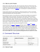
S01BLAUTO? Query enabled status of automatic BLDATA messages. S01BLAUTOx , where x is 0 or 1 depending on the current setting of BLAUTO. 8.32. BLDATA -- Request Level Information This command is used to request "blinking light" data from the EF2211. Blinking light data consists of signal levels for the 5 inputs (1, A, B, T), 4 outputs (1, A, B, T, L), and AEC reference (R1) as well as the room gain level for input 1, AGC gain level for input 1, and AEC state information for input 1.
translate to AEC states. Byte Value AEC State Value (Byte Value - 132) AEC State Description 132 0 Idle 133 1 Transmit 134 2 Receive 135 3 Double Talk Here's an example BLDATA message to clear things up. S01BLDATApèppçppppppèä The first four bytes (pèpp) consist of only two values. p = 0x70 = 112 → 112 - 132 = -20 è = 0x8A = 138 → 138 - 132 = 6 So, the signal at input A is at 6 dB, while the signals at the rest of the inputs are at -20 dB.
The last byte (ä) consists of only one value. ä = 0x84 = 132 → 132 - 132 = 0 = Idle So, we know that the AEC on input 1 is in idle mode. In the above description, the data in the BLDATA command consists of 13 bytes (4 input levels + 5 output levels + 1 AEC reference level + 1 room gain level + 1 AGC gain level + 1 AEC state). It is possible to tell the EF2211 to only send a subset of this information. There are two reasons you might want to do this.
Voice Business Group in Atlanta. Example Description Status Message S01BROAD2:ATDT4048921180 Sends the string ATDT4048921180 out the RSS01BROAD2 232 port. 8.35. BROADA -- Broadcast Commands to Other Connected Devices This command is used to broadcast commands to other connected Polycom devices via the EF Bus and/or ASPI Bus. For example, the command ' S01BROADA:B02PHONE1 ' would cause device ID 1 to send a command to the EF2241 at device ID 2 to tell it to take its phone off-hook.
Example Description Status Message Put AEC Reference 1 (R1) on the EF Bus. Set Vortex to not place any AEC reference on the EF Bus. S01BUSREF? Query which AEC reference this Vortex is placing on the EF Bus. , where x is 0 or 1 depending on which AEC reference (if any) is currently being placed on EF Bus. 8.37. CGATE -- Query Camera Gating Status Information This command is used to query the gating status of the microphone input.
This command is saved to non-volatile memory only as part of a preset. The state of this command will be restored after power-up only if a preset is saved and that preset is set to be the power-on preset. Example Description Status Message S01CGATEEN0 Disable automatic camera gating messages. S01CGATEEN0 S01CGATEEN1 Enable automatic camera gating messages. S01CGATEEN1 Toggle enabled state of automatic camera gating messages.
8.40. COUNTRY -- Specify Country Definitions for Phone Interface This command is used to set or query the country that the Vortex is configured for operation in. The country setting affects parameters associated with the phone interface including transmit and receive impedances, flash hook timing, timing thresholds for detecting hangup based on loop current drop, timing thresholds for detecting incoming rings, and outgoing DTMF levels.
S01DELAYOB1500 Set output delay on output channel B to 150 ms (1500 tenths of milliseconds). S01DELAYOB1500 S01DELAYOBx , where x is between 0 and 3400 depending on the current output delay Increase output delay on output setting for output channel B . If this S01DELAYOB>1700 channel B by 170 ms (1700 command is issued after the above example, tenths of milliseconds.) then the status message will be S01DELAYOB3200 . S01DELAYOB? Query current output delay on output channel B .
Enable output delay on outputs A and B, and disable S01DELAYOE*0110 S01DELAYOE*0110 output delay on outputs 1 and T. S01DELAYOE*2 S01DELAYOE*? Toggle enabled status of output delay on all outputs. S01DELAYOE*abcd , where each of the letters (a, b, etc.) is either 0 or 1 depending of the current enabled status of the output delay on the corresponding output. If this command was sent after the example above, then the status message would be S01DELAYOE*1001 .
S01DSPAUTO? Query the value of the DSPAUTO parameter. S01DSPAUTOx , where x is 0 or 1 depending on the current setting of the DSPAUTO paramter. 8.45. DSPLOAD -- Query Percentage of Variable DSP Resources Used This command queries the current percentage used of the available variable DSP resources. When this number reaches 100 percent, no more variable DSP veatures may ben enabled. An 'ERROR#060' will be generated if a command attempts to exceend 100 percent utilization.
ERROR#043 This error occurs as the result of an AMLMN command. It happens when the command attempts to set a "last mic on" number that does not belong to the specified automixer while "last mic on" mode is set to manual. ERROR#044 This error occurs as the result of an AMCHAIR command. It happens when the command tries to enable chairman mode, but the chairman microphone is set to a microphone that does not belong to the specified automixer.
ERROR#092 This error indicates an EF Bus ID conflict. See the Vortex user manual for information on valid device IDs. ERROR#093 This error indicates an EF Bus reference conflict. This error occurs when more than one Vortex is placing its AEC reference on the bus. Use the BUSREF command to remove the extra reference(s) in order to resolve the conflict. This command is a boolean command. See Section 6.1 for more information on this type of command.
S01FADERIAa S01FADERIBb , where a and b are the new values of the fader gains for each of the line inputs. If this command was issued after the example above, then the status messages would be: S01FADERIA10 S01FADERIB10 . S01FADERGIL>3 Increase fader gains on all line inputs by 3 dB. S01FADERGIL? S01FADERIAa S01FADERIBb , where a and b are the new values of the fader gains for each of the line inputs. If this Query fader gains on all line inputs.
S01FADERIA? Query the fader gain on input A. S01FADERIAx , where x is a number between 0 and 30, depending on the current setting of the fader gain on input channel A. S01FADERI*6 Set fader gain on all inputs (1, A, B, T) to 6 dB. S01FADERI*èèèè Set fader gain on input channels A and B to 0 dB and S01FADERI*ìääì S01FADERI*ìääì gain on input channels 1 and T to 9 dB. S01FADERI*? Query fader gain on all inputs (1, A, B, T) .
We recommend using hardware flow control whenever possible, especially when using higher baud rates. This command is saved to global non-volatile memory and is not part of a preset. Its value is saved each time it is changed. It will retain its value after power-down. Since this command writes to nonvolatile memory, there will be a delay before an acknowledgment is returned. Example Description S01FLOW1 Set rear panel RS-232 port to use hardware flow control.
8.52. FPPSWD -- Change Front Panel Password This command sets or queries the front panel password. This password is used in conjunction with the FPLOCK command. The front panel must be unlocked ('FPLOCK0') in order to use this command to set or query the front panel password. If the front panel is locked, then this command will result in 'ERROR#004'. The examples below assume that the front panel is unlocked. Example Description Status Message S01FPPSWDmonkey Set front panel password to 'monkey'.
This command is an integer command. See Section 6.2 for more information on this type of command. The minimum and maximum values for this command are -20 and 20, respectively. This command is saved to non-volatile memory only as part of a preset. The state of this command will be restored after power-up only if a preset is saved and that preset is set to be the power-on preset. Example Description Status Message S01GAIND6 Set incoming DTMF gain to 6 dB.
This command sets the gain of the dial tone received from the phone interface. This command is an integer command. See Section 6.2 for more information on this type of command. The minimum and maximum values for this command are -20 and 20, respectively. This command is saved to non-volatile memory only as part of a preset. The state of this command will be restored after power-up only if a preset is saved and that preset is set to be the power-on preset.
S01GAINGIL>3 S01GAINGIL? Increase incoming gain on all line inputs by 3 dB. S01GAINIAa S01GAINIBb , where a and b are the new values of each of the line inputs. If this command was issued after the example above, then the status messages would be: S01GAINIA10 S01GAINIB10 . Query gains on all line inputs. S01GAINIAa S01GAINIBb , where a and b are the new values of each of the line inputs. If this command was issued after the example above, then the status messages would be: S01GAINIA10 S01GAINIB10 . 8.
Example Description Status Message S01GAINIA10 Set gain on input A to 10 dB. S01GAINIA10 S01GAINIA? Query the gain on input A. F01GAINI2xB01GAINITxS01GAINIAxQ01GAINIAxT01GAINITx, where x is a number between 0 and 30, depending on the current setting of the gain on input channel A. S01GAINI*6 Set gain on all inputs (1, S01GAINI*èèèè A, B, T) to 6 dB. Set gain on input channels A and B to 0 S01GAINI*ìääì dB and gain S01GAINI*ìääì on input channels 1 and T to 9 dB.
Set gain on output channels 1 S01GAINO*äììä and T to 0 dB, and gain on S01GAINO*äììä output channels A and B to 9 dB. S01GAINO*? S01GAINO*abcd, where a-d are each Query gain settings on all output between and ÿ, depending on the channels (1, A, B, T) . current setting of the gains for each of the ten output channels (1, A, B, T). 8.60. GAINP -- Set Phone Output Gain This command sets the gain of the output to the phone interface. This command is an alias for the GAINOT.
will be restored after power-up only if a preset is saved and that preset is set to be the power-on preset. Example Description Status Message S01GAINSIT6 Set tone output gain to 6 dB. S01GAINSIT6 S01GAINSITx where x is the new value of the tone output gain. If this command was issued S01GAINSIT>3 Increase tone output gain by 3 dB. after the example above, then the status message would be S01GAINSIT9 . S01GAINSIT? Query tone output gain.
status of all the microphone inputs. On the EF2211 and EF2210, there is only one microphone, so the wildcard character is of limited use. The GATEEN can be used to have gating information sent automatically instead of having to poll this command. Also see the CGATE command, which only reports microphones that have been gated on for a specified hold time. Example Description Status Message S01GATE1? , where x is 0 or 1 depending S01GATE1? Query gating status of microphone input 1.
The name of this command is an abbreviation of "Global Mute Outputs." Enabling this option causes all of the physical outputs to be muted (outputs 1, A, B, T) . This muting is independent of the normal output mute command, MUTEO. This command is provided so that the control program can implement a "saftey mute" feature.
iLABELx,y where i is the device type and ID, x is the label specifier, and y is the label text (to set the label) or a ? character (to query the label). The label specifiers are as follows: Label Specifier Description D A label for the device itself. SG A label for the signal generator. I1, IA, IB, IT Labels for the input channels. O1, OA, OB, OT Labels for the output channels. P, W, X, Y, Z Labels for matrix outputs to EF Bus.
This command was introduced in firmware version 2.5.0. This command is a channel boolean command. See Section 6.3 and Section 6.1 for more information on this type of command. This command is saved to non-volatile memory only as part of a preset. The state of this command will be restored after power-up only if a preset is saved and that preset is set to be the power-on preset. Example Description Status Message S01LAGCB1 Enable AGC on input channel B.
preset. Example Description Status Message S01LAGCLINKAB1 Enable stereo AGC linking on inputs A and B. S01LAGCLINKAB1 S01LAGCLINKAB0 Disable stereo AGC linking on inputs A and B. S01LAGCLINKAB0 Toggle stereo AGC linking on S01LAGCLINKAB2 inputs A and B. S01LAGCLINKABx , where x is 0 or 1 depending on the current state of stereo AGC linking on inputs A and B. Query status of stereo AGC S01LAGCLINKAB? linking on inputs A and B.
LAGCMIN is set to -10, then the AGC for that channel can apply a minimum of -10 dB of gain to the input signal. This command was introduced in firmware version 2.5.0. This command is a channel integer command. See Section 6.3 and Section 6.2 for more information on this type of command. The minimum and maximum values for this command are -15 and 0, respectively. This command is saved to non-volatile memory only as part of a preset.
This command sets or queries the status of the line echo canceller (LEC). This command is a boolean command. See Section 6.1 for more information on this type of command. This command is saved to non-volatile memory only as part of a preset. The state of this command will be restored after power-up only if a preset is saved and that preset is set to be the power-on preset. Example Description Status Message S01LEC1 Enable LEC. S01LEC1 S01LEC0 Disable LEC. S01LEC0 S01LEC2 Toggle LEC state.
24 boolean values is returned with the first value indicating the state of the first logic input, the second value indicating the state of the second logic input, and so on. This command is saved to global non-volatile memory and is not part of a preset. Its value is saved each time it is changed. It will retain its value after power-down. Since this command writes to nonvolatile memory, there will be a delay before an acknowledgment is returned.
S01LIA4,MUTEI11 Assign the command MUTEI11 to occur when logic input pin 4 changes S01LIA4,MUTEI11 from the inactive to active state. The MUTEI11 mutes input channel 1 S01LIA5,MACROX23 Assign the command MACROX23 to occur when logic input pin 5 changes from the inactive state to S01LIA5,MACROX23 the active state. The MACROX23 command executes macro 23, which can contain up to 256 other commands.
This function assigns a single command to be executed when a given logic input changes from the active state to the inactive state. Typically, the inactive state is logic high ('1') and the active state is logic low ('0'). This is commonly referred to as active low. Acitve low is considered normal because a closed switch would ground the input and a closed switch would normally be considered active. This polarity setting can be changed via the LIP command.
MACROQ command. Since up to 256 commands can be stored in each macro, this gives the effect of having up to 256 commands execute when the logic pin changes state. The command associated with the state change can also be a PRESETX or PRESETQ. This makes it easy to reconfigure the device for different rooms based on external logic settings. The BROADA is also useful in logic pin assignments.
Example Description Status Message S01LIEN1 Enable automatic logic input status messages. S01LIEN1 S01LIEN0 Disable automatic logic input status messages. S01LIEN0 S01LIEN2 Toggle automatic logic input status messages. S01LIENx , where x is 0 or 1 depending on the current setting of LIEN. S01LIEN? Query automatic logic input status messages. S01LIENx , where x is 0 or 1 depending on the current setting of LIEN. 8.80.
8.81. LIK -- Delete One or All Logic Input Pin Commands This command "kills" or deletes all commands for a given logic input pin. In other words, the commands associated with LIA, LID, and LIH will be deleted for the specified logic input. A wildcard character can also be specified for the logic input pin, in which case the commands for all logic input pins will be deleted.
Mask (disable) logic S01LIM100101101111011111111111 S01LIM100101101111011111111111 inputs 2, 3, 5, 8, and 13. Query current S01LIMabcdefghijklmnopqrstuvwx logic input where a-x are each 0 or 1 depending on mask. the current state of the logic input mask. S01LIM? 8.83. LIN -- Assign Command to Logic Input Group This command assigns a command to be executed when a group of logic input pins is in a certain configuration. Logic groups are defined via the LIG command.
closed switch would ground the input, and a closed switch would normally be considered active. This command affects the operation of the LIA, LID, and LIH commands. If a logic input pin's polarity is reversed, the operation of these commands is reversed. By default, the polarity for all pins is set to normal (active low). This command is saved to global non-volatile memory and is not part of a preset. Its value is saved each time it is changed. It will retain its value after power-down.
State This command is used to define the conditions under which a given logic output pin goes into the active state. By default the logic output pins are active high. Active high is the default because it would light an LED connected to the output when the output was in the active state. The polarity of the logic output pins can be changed with the LOP command. The syntax of this command allows one to use one of the boolean channel commands to determine the state of the logic output pin.
S01LOA10,MUTEI*1+-. Configure the conditions for activation of logic output 10 as described in the example above. S01LOA10,MUTEI*1+-. S01LOA7, Delete conditions for activation of logic output 7. S01LOA7, 8.87. LOD -- Define Behavior for Logic Output Deactivated Status This command is used to define the conditions under which a given logic output pin goes into the deactive state. The syntax and behavior of this command is identical to that of the LOA command.
S01LOENx , where x is 0 or 1 S01LOEN? Query automatic logic output status messages. depending on the current setting of LOEN. 8.89. LOK -- Delete One or All Logic Output Pin Commands This command "kills" or deletes all commands for a given logic output pin. In other words, the commands associated with LOA and LOD will be deleted for the specified logic output. A wildcard character can also be specified for the logic output pin, in which case the commands for all logic output pins will be deleted.
Example Description Mask (disable) S01LOM10010110111101111111 logic outputs 2, 3, 5, 8, and 13. S01LOM? Query current logic output mask. Status Message S01LOM10010110111101111111 S01LOMabcdefghijklmnopqrst , where at are each 0 or 1 depending on the current state of the logic output mask. 8.91. LOP -- Set Polarity for Logic Outputs This command sets the polarity for the 20 logic input pins. Setting the polarity for a given pin to 1 indicates that the polarity should be normal (active high).
● ● ● any PRESET command any MACRO command any logic input or output command If an attempt to assign an invalid command to a macro is made (via MACROA), then the error condition ERROR#074 will be generated. An error will be generated if the specified command is not a valid command. However, an error will not be generated if the specified command is valid, but its data is invalid. For example: S01MACROA25,LAYDOWNTHEBOOGIE Would return an error because it does not contain a valid command.
S01MACROK* Delete all the commands associated with all 255 macros. S01MACROK* 8.94. MACROL -- List All Commmands in a Macro This command lists all the commands in a given macro. For example, assume that a macro has been defined via the following command sequence.
This command is used to start writing a new macro with a specified macro number. This command is used in conjunction with the MACROA and MACROW commands to create a new macro. If this command is sent while another macro is in the process of being written (before the MACROW command is sent), then the macro in progress will be deleted and the new one will be started. See the description of the MACROA command for detailed information on creating macros. 8.97.
This command selects which signal is displayed on the front panel LED meter. The options correspond to either the telepone input or telephone output. The labels for the the telephone input and output are IT and OT, respectively. This command is saved to non-volatile memory only as part of a preset. The state of this command will be restored after power-up only if a preset is saved and that preset is set to be the power-on preset.
S01MGAINWB0,WM0,-3 Set crosspoint gain in EF Bus submatrix on crosspoint that routes the W bus S01MGAINWB0,WM0,-3 signal from the device at ID0 (WB0) to W submatrix output 0 (WM0). Set all crosspoint gains for input channel 1. Set the gain to output 1 to 0 dB (ä), the gain to outputs A-B to -9 dB ({), the gain to the S01MGAIN1,*,ä{{èäÇÇÇÇÇ S01MGAIN1,*,ä{{èäÇÇÇÇÇ telephone output to 6 dB (è), the gain to AEC reference 1 to 0 dB (ä), and the gain to bus outputs P, W, X, Y, and Z to -3 dB (Ç).
This command is a matrix boolean command. See Section 6.4 and Section 6.1 for more information on this type of command. This command is saved to non-volatile memory only as part of a preset. The state of this command will be restored after power-up only if a preset is saved and that preset is set to be the power-on preset. Example Description Status Message Select the gated version of S01MGATE1,A,1 microphone input 1 to be sent to output A.
S01MIC1? Query enabled status of microphone gain stage for input channel 1. S01MIC1x , where x is 0 or 1 depending on the current enabled state of the microphone gain stage on input channel 1. 8.103. MINI -- Enable Modem Initialization String This command controls whether or not the modem initialization string is sent at power-up. If MINI is 0, then the modem initialization string is not sent. If MINI is 1, then the modem initialization string is sent.
Example Description Status Message Set modem initialization S01MINISTRATF1E0&B1S0=2 string to ATF1E0&B1S0=2. S01MINISTR? Query current modem initialization string. S01MINISTRATF1E0&B1S0=2 S01MINISTR , where is the current modem initialization string. If this command was sent after the above example, then the status message would be S01MINISTRATF1E0&B1S0=2 . 8.105.
Set all crosspoint mutes for input channel 1. Mute the paths from input 1 S01MMUTE1,*,0110100000 to outputs A, B, and S01MMUTE1,*,0110100000 P and unmute the paths from input 1 to outputs 1, T, R1, and W-Z. S01MMUTEA,*,0 Unmute all crosspoints for input S01MMUTEA,*,0000000000 channel A . S01MMUTEA,*,2 S01MMUTEA,*,abcdefghij , where the value of each of letters (a, b, etc.) is either 0 or 1 Toggle all crosspoint depending on the current state of each of the mutes for input crosspoint mutes.
S01MUTEGIL2 Toggle mute status of all line inputs. S01MUTEIAa S01MUTEIBb , where a and b reflect the mute status (0 or 1) of each of the line inputs. If this command was issued after the example above, then the status messages would be: S01MUTEIA0 S01MUTEIB0 . Query the mute status of all the line inputs. S01MUTEIAa S01MUTEIBb , where a and b reflect the mute status (0 or 1) of each of the line inputs.
S01MUTEI*2 S01MUTEI*? Toggle mute status of all inputs. S01MUTEI*abcd , where each of the letters (a, b, etc.) is either 0 or 1 depending of the current status of the mute on the corresponding input. If this command was sent after the example above, then the status message would be S01MUTEI*0110 . Query mute status of all inputs. S01MUTEI*abcd where each of the letters (a, b, etc.) is either 0 or 1 depending of the current status of the mute on the corresponding input.
S01MUTEO*? Query mute status of all outputs. S01MUTEO*abcd , where each of the letters (a, b, etc.) is either 0 or 1 depending of the current status of the mute on the corresponding output. If this command was sent after the example above, then the status message would be S01MUTEO*0110 8.109. NC -- Enable Noise Cancellation This command sets or queries the status of the Noise Cancellation (NC) algorithm on input channels 1 and T .
cancel 10 dB of noise. Higher numbers mean more cancellation will be applied, but may result in slight artifacts depending on the characteristics of the noise. Typical settings are 10 dB for normal cancellation and 6 dB for light cancellation. When the wildcard character, '*', is used to specify the channel in this command, it only affects input channel 1. To set or query the telephone input channel, T, you must specify it explicitly (e.g., '' '' 'S01NCLT6', '' '' 'S01NCLT?').
This command controls the non-volatile memory lock feature. When NVLOCK is enabled, the user may not save any system settings to non-volatile memory. This includes global parameters, presets, macros, labels, and logic assignments. The lock applies whether the user tries to make the changes via RS-232, front panel, logic inputs, or any other method. The user will still be able to query all the features of the device, but will get an error message if an attempt is made to change them.
Query the current non-volatile memory password. S01NVPSWD? S01NVPSWDlemur 8.114. PEQIA -- Set All Parameters for Specified Parametric EQ Input Stage This command sets or queries all of the parameters for the parametric equalizer (EQ) filters on input channels 1, A, B, and T input channel T. Each channel has five bands of parametric EQ that can be independently controlled. The input parametric EQ filter parameters can be set individually via the PEQIT, PEQIF, PEQIB, PEQIG, PEQIS, and PEQIE commands.
Parametric (1) Yes Yes Yes No Low Shelf (2) No Yes Yes Yes High Shelf (3) No Yes Yes Yes Lowpass (4) No Yes No No Highpass (5) No Yes No No Linkwitz-Riley Lowpass (6) No Yes No Yes Linkwitz-Riley Highpass (7) No Yes No Yes When a parameter is invalid for a given filter type, the parametric EQ commands will still set that parameter, however its value will not be used for filter computations.
S01PEQIAB,1,t,f,b,g,s,e , where the parameters t, f, b, g, s, and e Query the current correspond to the current settings of the parameter type, frequency, bandwidth, gain, slope, settings for the and enabled parameters, respectively. If parametric eq this filter was set to the same parameters filter on input B , as given in the above example, the status band 1. message would be S01PEQIAB,2,1,1250,40,-20,1,1 . S01PEQIAB,1,? 8.115.
the parametric equalizer (EQ) filters on input channels 1, A, B, and T . Each channel has five bands of parametric EQ that can be independently controlled. This command has the same format and restrictions as the PEQIA command except that only one parameter, the enabled status, is specified instead of all the parameters. See the PEQIA command for more information. To set the enabled parameter for an output parametric EQ filter, use the PEQOE command.
Set frequency of parametric S01PEQIF1,2,1250 EQ on input 1 , band 2 to 1250 Hz. S01PEQIFB,1,? Query current frequency setting of parametric EQ on input B , band 1. S01PEQIF1,2,1250 S01PEQIFB,1,f , where f is the current setting of the frequency parameter for the parametric EQ on input B , band 1. If the frequency parameter of this filter is set to the same value given in the example above, then the status message will be S01PEQIFB,1,1250 . 8.118.
(EQ) filters on input channels 1, A, B, and T . Each channel has five bands of parametric EQ that can be independently controlled. For the Linkwitz-Riley filters, the slope can either be 12 or 24 (dB/Octave).For the low shelf and high shelf filters, the minimum value for the slope parameter is 1, and the maximum value is 1.2 times the current value of the gain parameter. See the PEQIG command for information on the gain parameter.
parameter, the filter type, is specified instead of all the parameters. See the PEQIA command for more information. To set the slope parameter for an output parametric EQ filter, use the PEQOT command. To set all the parameters for an output parametric EQ filter, use the PEQOA command. This command is saved to non-volatile memory only as part of a preset. The state of this command will be restored after power-up only if a preset is saved and that preset is set to be the power-on preset.
Gain -20 - 20 dB Slope 1 - 1.2 * Gain for shelving filters, 12 or 24 for LinkwitzRiley filters dB per octave Enable 0-1 0 = filter disabled 1 = filter enabled The paramters are specified in the order shown and are separated by commas. The wildcard character, *, may not be used for any of the parameters listed above. If an attempt is made to set one of the parameters outside the valid range, the command will fail and return an error message of ERROR#002.
Set the parametric EQ on output 1 , band 2 to the following parameters: type = parametric filter, frequency = 1250 Hz, bandwidth = 40 1/100th octaves, S01PEQOA1,2,1,1250,40,-20,1,1 gain = -20 dB, S01PEQOA1,2,1,1250,40,-20,1,1 enabled = yes, slope = 1 dB per octave. The value of the slope parameter is irrelevant for this type of filter, we could have set it to anything.
preset. Example Description Status Message Set bandwidth of parametric EQ S01PEQOB1,2,40 on output 1 , band 2 to 40 S01PEQOB1,2,40 1/100th octaves. S01PEQOBB,1,? S01PEQOBB,1,b , where b is the current setting of the bandwidth parameter for the Query current bandwidth setting parametric EQ on output B , band 1. If the of parametric EQ on output B , bandwidth parameter of this filter is set to the band 1. same value given in the example above, then the status message will be S01PEQOBB,1,40 . 8.123.
This command sets or queries the frequency parameter (in Hz) for the parametric equalizer (EQ) filters on output channels 1, A, B, and T . Each channel has five bands of parametric EQ that can be independently controlled. The minimum and maximum values for the frequency parameter are 20 and 20000, respectively. For filter types that have a center frequency (e.g., parametric), this parameter specifies the center frequency. For filter types that have a cutoff frequency (e.g, highpass, lowpass, etc.
This command is saved to non-volatile memory only as part of a preset. The state of this command will be restored after power-up only if a preset is saved and that preset is set to be the power-on preset. Example Description Set the gain of the parametric S01PEQOG1,2,-20 EQ on output 1 , band 2 to -20 dB. S01PEQOGB,1,? Query current gain setting of parametric EQ on output B , band 1.
S01PEQOSB,1,s , where s is the current setting of the slope parameter for the Query current slope setting of parametric EQ on output B , band 1. If the S01PEQOSB,1,? parametric EQ on output B , band slope parameter of this filter is set to the same 1. value given in the example above, then the status message will be S01PEQOSB,1,1 . 8.127.
S01PEQOTB,1,t , where t is the current setting of the type parameter for the Query current type setting of parametric EQ on output B , band 1. If the S01PEQOT1,2,1 parametric EQ on output B , band type parameter of this filter is set to the same 1. value given in the example above, then the status message will be S01PEQOTB,1,1 . 8.128. PHANTOM -- Enable Phantom Power on Input 1 This command sets or queries the status of phantom power on microphone input 1. This command is a channel boolean command.
Toggle hook status of phone interface. If S01PHONEx , where x is either 0 or 1 the phone was off-hook, then this command S01PHONE2 depending on the current hook status of puts it on-hook. If the phone was on-hook, the phone interface. then this command takes it off-hook. S01PHONE? Query the hook status of phone interface. S01PHONEx , where x is either 0 or 1 depending on the current hook status of the phone interface. 8.130.
Example Description Status Message S01PRESETK18 Delete preset number 18. S01PRESETK18 S01PRESETK* Delete all presets. S01PRESETK* 8.132. PRESETL -- List All Commmands in a Preset This command lists all the commands in a given preset. For example, assume that user preset 18 has been defined previously by the following command. S01PRESETW18 Now, issuing the command: S01PRESETL18? Will result in a long sequence of status mesages reflecting all the data stored in the preset.
This command executes the preset corresponding to the specified number, which must be between 0 and 47. The preset must either be a pre-defined factory preset (0 - 15) or a user preset (16 - 47) that has been previously defined via the PRESETW command. If the specified preset is empty, then an error condition of ERROR#070 will be returned. If one or more of the commands in the preset generated errors, then an error condition of ERROR#072 will be returned.
Example Description Status Message Status messages for all the commands in the preset will S01PRESETX18 Execute preset number 18. be generated first, followed by the message: S01PRESETX18 8.137. REDIAL -- Redial the Last Dialed Phone Number Executing this command causes the Vortex to redial the last number. The last number is defined as all the digits that were dialed since the phone was last taken off-hook.
This command sets the effective output gain of the corresponding AEC reference. When doing volume control of room speakers, it is a good idea to adjust this reference gain along with the speaker output gain so that the AEC is aware of any volume changes. This will help prevent short echoes when volume changes are made.
S01RING1 Enable auto answer mode. S01RING1 S01RING0 Disable auto answer mode. S01RING0 S01RING2 Toggle auto answer mode. S01RINGx , where x is 0 or 1 depending on the current state of auto answer mode. S01RING? Query auto answer mode. S01RINGx , where x is 0 or 1 depending on the current state of auto answer mode. 8.141. SGGAIN -- Set Gain of Signal Generator This command sets the gain of the internal signal generator. The value of SGGAIN specifies the gain in dB applied to signal generator.
S01SGMUTE2 Toggle mute on signal generator. S01SGMUTEx , where x is 0 or 1 depending on the current state of the signal generator mute. S01SGMUTE? Query signal generator mute. S01SGMUTEx , where x is 0 or 1 depending on the current state of the signal generator mute. 8.143. SGTYPE -- Set Type of Signal Produced by Signal Generator This command sets the type of signal produced by the internal signal generator. Setting the type to 0 produces white noise, while setting the type to 1 produces pink noise.
6 quick double buzz 7 long single buzz The SOUNDL and SOUNDP were originally implemented to allow users to implement custom passcode systems that require users calling in via phone to enter a passcode before entering the conference. The sound commands could be used to provide feedback to the caller as well as the conference. Example Description Status Message S01SOUNDL0 Play "ascending thirds" sound (same as entry tone) locally. S01SOUNDL0 8.145.
This command sets or queries the amount of time (in milliseconds) between each new screen of the LCD screen saver. This command is an integer command. See Section 6.2 for more information on this type of command. The minimum and maximum values for this command are 500 and 600000, respectively. This command is saved to non-volatile memory only as part of a preset. The state of this command will be restored after power-up only if a preset is saved and that preset is set to be the power-on preset.
This command sets or queries the amount of time (in milliseconds) that the front panel buttons must be idle before the screen saver starts. This command is an integer command. See Section 6.2 for more information on this type of command. The minimum and maximum values for this command are 500 and 600000, respectively. This command is saved to non-volatile memory only as part of a preset.
S01SSTEXT0,1,? Query the text of the second line of the first screen. S01SSTEXT0,1, , where is the text of the second line of the first screen. If this command was issued after the example above, then the status message would be S01SSTEXT0,1,funky music . 8.150. SWRESET -- Perform Soft Reset of System Executing this command causes the Vortex to perform a software reset. The effect of the software reset is similar to cycling the power.
S01TONEE2 Toggle enabled status of entry and exit tones. S01TONEEx , where x is 0 or 1 depending on the current enabled state of entry and exit tones. S01TONEEx , where x is 0 or 1 S01TONEE? Query enabled state of entry and exit tones. depending on the current enabled state of entry and exit tones. 8.153. TONER -- Enable or Disable Ring Tones This command sets or queries the enabled status of the ring tone feature.
S01VTXMODIB0 Disable VTX mode on input B. S01VTXMODIB0 S01VTXMODIB2 Toggle status VTX mode on input B. S01VTXMODIBx , where x is either 0 or 1 depending on the current status of VTX mode on input B. S01VTXMODIA? Query status of VTX mode on input A. S01VTXMODIAx , where x is either 0 or 1 depending on the current status of VTX mode on input A. S01VTXMODI*1 Enable VTX mode on inputs A-B. S01VTXMODI*11 S01VTXMODI*0 Disable VTX mode on inputs A-B.
S01VTXMODOAx , where x is either 0 or 1 depending on the current status of VTX mode on output A. S01VTXMODOA? Query status of VTX mode on output A. S01VTXMODO*1 Enable VTX mode on outputs 1, S01VTXMODO*111 A-B. S01VTXMODO*0 Disable VTX mode on outputs 1, S01VTXMODO*000 A-B. Enable VTX mode on output 1 S01VTXMODO*100 and disable VTX mode on output A-B. S01VTXMODO*2 S01VTXMODO*? S01VTXMODO*100 Toggle status of VTX mode on outputs 1, A-B. S01VTXMODO*abc , where each of the letters (a, b, etc.