
Installation guide
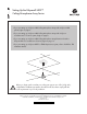


Setting up the Polycom HDX Ceiling Microphone Array Series
Setting up the Polycom HDX Ceiling Microphone Array for
Polycom HDX Systems
2
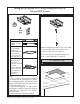
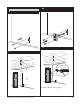
2’ (.6 m)
18” (.5 m) RJ-45
to Walta connector
adapter
10’ (3.1 m) non-
plenum straight-
through (use
between wall plate
and codec only;
do not use for any
other application)
50’ (15.2 m)
plenum crossover
(use between
electronics enclosure
and codec,
between electronics
enclosure and wall
plate, or between
two electronics
enclosures)
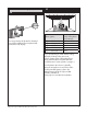
Notes:
• If your ceiling is 10 feet (3.05 m) or higher,
you should order an optional 6-foot (1.82 m)
drop cable (part number 2215-09591-002 for
black or 2215-09591-001 for white) for each
Ceiling Microphone Array.
• If you are creating your own cables, refer to
the Integrator’s Reference Manual for Polycom
HDX Systems for cable pin-outs. You can find
this document at
www.polycom.com/videodocumentation.
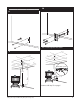
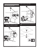
1
NOTE: Verify that the number of pins on the cable
connector matches the number of pins on the
connector on the electronics enclosure.
If you do not have a suspended ceiling in your
room, continue with Step 12 on page 5.
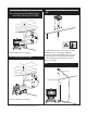
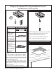
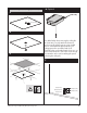
For suspended ceilings
2