RMX® 4000 Installation & Configuration Guide General Safety Precautions Follow these rules to ensure general safety: • • • • • • • • • Keep the area around the Polycom RMX® 4000 unit clean and free of clutter and well ventilated. Decide on a suitable location for the equipment rack that will hold the RMX, ensuring that it is near a grounded power outlet. Ensure that the leveling jacks on the bottom of the rack are fully extended to the floor with the full weight of the rack resting on them.
Preparations Obtain the following information from your network administrator: • IP addresses, Subnet Mask and Default Gateway IP address (optional) for the RMX control unit and RMX Shelf Management. • IP addresses for the RMX Signaling Host and Media cards. • Gatekeeper IP address. • SIP server IP address, if applicable.
Management Network Configuration on the USB Key The system is shipped with the following default IP addresses: • Control unit IP address – 192.168.1.254 • Shelf Management IP Address – 192.168.1.252 • Control unit subnet mask – 255.255.255.0 • Default Router IP Address – 192.168.1.1 When the RMX is installed for the first time, you must change the default IP addresses to your local network settings.
3 Fasten the RMX to the rack with screws through the eight holes in the RMX’s front mounting brackets. Connecting the cables to the RMX 4000 Connect the following cables to the RMX 4000 rear panel: • For AC Power Supply connections: Insert a power cable in each of the three AC Power Entry Modules (PEM’s). For DC Power connections, see the RMX 4000 Hardware Guide. The size of the protective earthing conductor & cable should be a minimum of 10AWG.
During the first-time power-up the red ERR LED on the RMX’s front panel remains ON until both the Management and IP Network Services have been defined. When the RMX's configuration is completed (including the Management and IP Network Services), and if there are no System Errors, the green RDY LED on the CNTL module (on the RMX’s front panel) turns ON. 3 Remove the USB key.
The Product Activation dialog box is displayed with the serial number filled in. 3 In the Activation Key field, enter or paste the Product Activation Key retrieved earlier and click OK. If you do not have an Activation Key, click the Polycom Resource Center button to access the Service & Support page of the Polycom website. The system prompts with a System Reset dialog box. 4 In the System Reset dialog box, click No.
Field Description Signaling Host IP Address Enter the IP address of the Central Signaling host. This is the address used by endpoints for dialing in to the MCU. Media Card 1/2/ 3/4 IP Address Enter the IP address(es) of the media card (s): MPM+ / MPMx 1, MPM+/MPMx 2, MPM+/MPMx 3 and MPM+/ MPMx 4 (if installed), as provided by the network administrator. Endpoints connect to conferences and transmit call media (video, voice and content) via these addresses. Subnet Mask Enter the subnet mask of the MCU.
Field Description Register Host Names Automatically to DNS Server Select this option to automatically register the MCU Signaling Host and Shelf Management with the DNS server. Local Domain Name Enter the name of the domain where the MCU is installed. Primary DNS Server IP Address The static IP addresses of the primary DNS server. 6 Click the Next button. 7 In the Fast Configuration Wizard - Environment dialog box, select the IP Network Type: H.323, SIP or H.323 & SIP. 8 Click Next.
Field Description Aliases Alias The alias by which the RMX’s Control Unit is identified within the network. Up to five aliases can be defined for each RMX. Note: When a gatekeeper is specified, at least one prefix or alias must be entered in the table. Type Select the type that defines the format in which the card alias is sent to the gatekeeper. • H.323 ID (alphanumeric ID) • • • • • E.
Field Description Transport Type Select the protocol that is used for signaling between the MCU and the SIP Server or the endpoints according to the protocol supported by the SIP Server: UDP – Select this option to use UDP for signaling. TCP – Select this option to use TCP for signaling. TLS – The Signaling Host listens on secured port 5061 only and all outgoing connections are established on secured connections. Calls from SIP clients or servers to non secured ports are rejected.
A new ISDN/PSTN Network Service can be defined even if no RTM ISDN card is installed in the system but only via the ISDN/PSTN Network Service ->Add New Service dialog box. The Fast Configuration Wizard’s ISDN/PSTN configuration sequence begins with the ISDN/PSTN dialog box. 17 Define the following parameters: Field Description Network Service Name Specify the service provider’s (carrier) name or any other name you choose, using up to 20 characters.
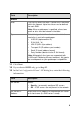
19 In the PRI Settings dialog box, define the following parameters: Field Description Default Num Type Select the Default Num Type from the list. The Num Type defines how the system handles the dialing digits. For example, if you type eight dialing digits, the Num Type defines whether this number is national or international. If the PRI lines are connected to the RMX via a network switch, the selection of the Num Type is used to route the call to a specific PRI line.
21 In the Span Definition dialog box, define the following parameters: Field Description Framing Select the Framing format used by the carrier for the network interface from the list. • For T1 spans, default is SFSF. • Side For E1 spans, default is FEBE. Select the RMX side on the network. Default: User side Note: If the PBX is configured on the network side, then the RMX unit must be configured as the user side, and vice versa, or both must be configured symmetrically.
26 Optional. Repeat steps 23 to 25 to define additional dial-in ranges. 27 Enter the MCU CLI (Calling Line Identification). With dial-in connections, the MCU CLI indicates the MCU’s number dialed by the participant. In a dial-out connection, indicates the MCU (CLI) number as seen by the participant. 28 Click Save & Continue. After clicking Save & Continue, you cannot use the Back button to return to previous configuration dialog boxes. The ISDN/PSTN Network Service is created and confirmed.
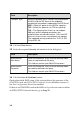
Additional ISDN/PSTN Network Services can be defined by selecting in the RMX Management pane ISDN/PSTN Network Services and then New ISDN/PSTN Service in the ISDN/PSTN Network Services list. 31 Click Next. The System Flags dialog box is displayed. 32 In the Fast Configuration Wizard - System Flags dialog box, enter the following information: Flag Value Conference ID Length (MCU) The number of digits of the Conference ID that will be assigned by the MCU.
Flag Value Auto Extend Conferences When Yes is selected (default) allows conferences running on the RMX to be automatically extended as long as there are participants connected and there are available resources. These flags can be modified later, if required, via the Setup menu’s System Configuration option. For more information, see the RMX 1500/2000/4000 Administrator’s Guide, "System Configuration” on page 18-5. 33 Click Save & Close. The RMX confirms successful configuration.
The system is now fully configured and if there are no System Errors, the green RDY LED on the CNTL module (on the RMX’s front panel) turns ON. User Definition The RMX is shipped with a default Administrator user called POLYCOM. Once you have defined other authorized administrator users, it is recommended to remove the default user to prevent unauthorized users from logging into the system. To add a new user to the system: 1 In the RMX Management pane, click the Users option. The Users pane appears.
Selecting the RMX Web Client Languages By default, the RMX Web Client interface is displayed only in English. However, the system administrator can choose the languages available for selection on the Login screen. To customize the Multilingual Setting: 1 On the RMX menu, click Setup > Multilingual Setting. The Multilingual Setting dialog box is displayed. 2 Place check marks in the boxes of the languages to be available for selection. 3 Click OK.
For more information on ISDN Network Services, see the RMX 1500/ 2000/4000 Administrator’s Guide, "ISDN/PSTN Network Services” on page 13-44. If additional Entry Queues and Meeting Rooms are required, for example, for conferencing at different line rates, you can customize the conferencing entities to your organization’s requirements and define additional conferencing entities. For more details, see the RMX 1500/ 2000/4000 Administrator’s Guide.
ISDN/PSTN Participants ISDN and PSTN participants can connect to conferences and Meeting Rooms directly or via an Entry Queue by dialing one of the numbers (including the country and area code if needed) assigned to the conference, Meeting Room or Entry Queue. When connecting to an EQ they are routed to their conference according to the conference ID.