Polycom® RMX® 4000 Hardware Guide Version 7.0.
Trademark Information Polycom®, the Polycom “Triangles” logo, and the names and marks associated with Polycom’s products are trademarks and/or service marks of Polycom, Inc., and are registered and/or common-law marks in the United States and various other countries. All other trademarks are the property of their respective owners. Patent Information The accompanying product is protected by one or more U.S. and foreign patents and/or pending patent applications held by Polycom, Inc. © 2010 Polycom, Inc.
CE MARK R&RTTE Directive Česky [Czech]: Dansk [Danish]: Deutsch [German]: Eesti [Estonian]: English: Español [Spanish]: Ελληνική [Greek]: Français [French]: Italiano [Italian]: Íslenska (Icelandic): Latviski [Latvian]: Lietuvių [Lithuanian]: Nederlands [Dutch]: Malti [Maltese]: Magyar [Hungarian]: Norsk [Norwegian]: Polycom (UK) Ltd tímto prohlašuje, že tento RMX 4000 je ve shodě se základními požadavky a dalšími příslušnými ustanoveními směrnice 1999/5/ES.
Polski [Polish]: Português [Portuguese]: Slovensko [Slovenian]: Slovensky [Slovak]: Suomi [Finnish]: Svenska [Swedish]: Niniejszym Polycom (UK) Ltd oświadcza, że RMX 4000 jest zgodne z zasadniczymi wymaganiami oraz innymi stosownymi postanowieniami Dyrektywy 1999/5/WE Polycom (UK) Ltd declara que este RMX 4000 está conforme com os requisitos essenciais e outras disposições da Directiva 1999/5/CE.
Polycom RMX 4000 Hardware Guide Table of Contents Hardware Description . . . . . . . . . . . . . . . . . . . . . . . . . . 1-1 Main Features .......................................................................................... 1-1 RMX 4000 Specifications ....................................................................... 1-2 RMX 4000 System Capacities ........................................................ 1-3 Conferencing Capacities ........................................................
Table of Contents RMX 4000 Components ....................................................................... 1-23 RMX 4000 Front Panel ................................................................. 1-23 RMX 4000 Rear Panel ................................................................... 1-27 RTM-IP 4000 .................................................................................. 1-28 RTM ISDN .....................................................................................
1 Hardware Description This Hardware Guide provides information on the RMX 4000 and its components. This system utilizes a modular “universal slot” platform, whose components are designed for high performance, capacity and reliance.
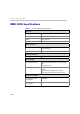
Chapter 1- Hardware Description RMX 4000 Specifications Table 1-1 Polycom RMX 4000 Specifications Physical Height 6U (26.56 cm.) Width 19” (48.26 cm.) Depth 15.74” (40 cm.) Weight Up to 40 Kg. Media Protocols Audio G.711, G. 719, G.722, G.722.1, G.729A, G.723.1, Siren14, Siren 22. Video H.261, H.263, H.264. Network Interfaces IP, ISDN, PSTN and LAN H.323, SIP, PSTN, LAN and ISDN. Power Supply AC Input/ Range, BTU Voltage range:100-240 VAC, 14-7 AMP, 50/60 Hz. BTU output: 5120.
Polycom RMX 4000 Hardware Guide Table 1-1 Polycom RMX 4000 Specifications (Continued) Environment Operating temperature 10°– 40°C (50°– 104°F). Storage temperature -40°– 70°C (40°– 158°F). Relative humidity 15% - 90% no condensing. Operating altitude 60m below sea level, up to 3,000 m (10,000 ft.). Operating ESD 4kV. RMX 4000 System Capacities Conferencing Capacities The following table summarizes the different system capacities.
Chapter 1- Hardware Description Table 1-2 1-4 System Functions and Capacities RMX 4000 System Functions MPM+ Mode MPMx Mode Maximum number of IP Services 1 1 Maximum number of ISDN Services 2 2 Maximum number of IVR Services 80 80 Maximum number of Recording Links 20 (default) 20 (default) Maximum number of IVR Video Slides 150 150 Maximum number of Log Files (1Mb max.
Polycom RMX 4000 Hardware Guide Resource Capacities per Card Assembly MPMx Card Two MPMx card assemblies are available: MPMx -S (Single) and MPMx-D (Double) each offer different resource capacities, as summarized in Table 1-3: Table 1-3 MPMx – Resource Capacity per Card Resource Type MPMx - S MPMx - D Voice 180 360 H.263 CIF 30 60 H.263 4CIF15 15 30 H.264 CIF/VSW 45 90 SD H.
Chapter 1- Hardware Description Resource Capacities per Card Type (MPM, MPM+ and MPMx) Each MPMx card increases the resource capacities. HD720p60 and HD1080p30 symmetric resolutions are supported with MPMx. Table 1-5 summarizes resource capacities of the various cards that can be installed in an RMX.
Polycom RMX 4000 Hardware Guide MCU Card Configuration Mode Guidelines MPMx and MPM+ Modes • MPMx and MPM+ cards installed in the system cannot be used simultaneously. Therefore, the RMX can operate in either MPM+ or MPMx Card Configuration Mode. • MPMx Mode is the mode in which the RMX operates to fully utilize the increased power and capacity of MPMx cards. • ISDN support is the same as for both MPM+/MPMx cards. • G.719 audio algorithm is not supported with MPMx.
Chapter 1- Hardware Description Safety Requirements This section describes the requirements your site must meet for safe installation and operation of the system. Site Safety Requirements For your protection, please read these safety instructions completely before operating the equipment. 1-8 • Look carefully for potential hazards in your work area: moist floors, ungrounded power cables, frayed power cords, missing safety grounds and so forth. • Locate the main circuit breaker within the room.
Polycom RMX 4000 Hardware Guide General Installation Precautions Attention: The RMX 4000 can weigh up to 40kg when all slots are occupied. Two people are required to lift the MCU out of the box and also when installing it in a rack. • Use a regulating uninterruptable power supply (UPS) to protect the RMX 4000 from power surges and voltage spikes, to keep your MCU operating in case of a power failure.
Chapter 1- Hardware Description • Always keep the rack’s trays and card’s slots closed when not servicing, to maintain proper cooling.
Polycom RMX 4000 Hardware Guide Make sure that boxes contain all the required parts. 4 Remove the boxes and top Stratocell®. 5 Holding the handle on each side, lift the RMX 4000 from the box, and place it on a flat surface or install it in a rack. Remove any packaging material prior to positioning the RMX 4000. Attention: Two people are required to lift the MCU out of the box and when installing it in a rack.
Chapter 1- Hardware Description Installing the RMX in a Rack or as a Standalone Either place the RMX 4000 on a hard, flat surface such as a desktop or mount it on a 19”/23” rack. Standalone RMX 4000 Installation Place the RMX 4000 on a flat surface or desktop. The RMX 4000 must rest on the four feet at the base of the MCU and must be shifted or moved into position using the two handles attached to the front.
Polycom RMX 4000 Hardware Guide Placing the RMX 4000 in a 19” Rack 1 When the RMX is to be rack mounted chassis runners must be installed on the rack as shown in Figure 1-2. Two chassis runners are included in the Rack Installation Accessories kit and are attached facing inward from the outside of the 19”/23“rack mount. Figure 1-2 Installing chassis runners and RMX in a rack 2 Mount the RMX on top of the rack brackets using the blades or placing it on a rack mount shelf with runners.
Chapter 1- Hardware Description 3 Fasten the RMX to the rack with 8 screws into the holes provided on the RMX’s front as shown in Figure 1-3. Figure 1-3 RMX 4000 Rack Mount Rack mounting screws must be supplied by the rack’s manufacturer. The airflow of the RMX 4000 is from right to left. Be sure that the areas on the left and right side of the system are clear for proper ventilation. When the unit is installed on a rack, the rack must be properly grounded to the central office ground.
Polycom RMX 4000 Hardware Guide Placing the RMX 4000 in a 23” Rack 1 Mounting the RMX 4000 on a 23” rack requires that first the handles and then the 19” brackets be removed from the MCU. This is shown in Figure 1-4. Figure 1-4 Removing and attaching 19” and 23” brackets 2 After removal, attach the 23” brackets as provided in the Rack Installation Accessories kit, and re-install the handles to the 23” brackets. This is shown in Figure 1-5.
Chapter 1- Hardware Description The airflow of the RMX 4000 is from right to left. Be sure that the areas on the left and right side of the system are clear for proper ventilation. When the unit is installed on a rack, the rack must be properly grounded to the central office ground. The rack must be grounded with two-hole compressiontype connectors using copper conductors (tinned or untinned). Wire, bus bar or braided strap connectors are acceptable.
Polycom RMX 4000 Hardware Guide 3 Place the RMX in a rack and tighten the 8 screws securing the RMX to the rack. Connecting the RMX 4000 to Power Sources You can connect either an AC Inlet or to DC power according to the power system required at your site: • For systems with AC Power, up to three power supplies can be installed with one being redundant (n+1).
Chapter 1- Hardware Description • Listed fastening hardware must be compatible with the materials being joined and must be preclude loosening, deterioration and electrochemical corrosion of the hardware and joint materials. Connecting the RMX 4000 to AC Power 1 • Do not connect the green or green-yellow wire to the system single-point ground screw. • • Customers are required to only use AC power cables supplied by Polycom.
Polycom RMX 4000 Hardware Guide Connecting the RMX 4000 to -48DC SELV Power 1 On the DC Power Rail Modules (PRM’s), set the two circuit breakers to OFF. For more information on circuit breaker types, see "Types of DC Circuit Breakers installed on the RMX 4000” on page 1-20. 2 Ensure that the cables from the Main that supplies electricity to the DC power units are OFF or disconnected. 3 Remove the transparent plastic caps on the terminal block.
Chapter 1- Hardware Description 5 Connect the green or green-yellow wire to the system single-point M6x15 “Ground” bolt. The rating of the protective earthing conductor should be a minimum of 10AWG. If the unit is rack mounted, the single-point ground on the MCU must be connected to the rack with a single conductor and fixed as to prevent loosening. When using bare conductors, they must be coated with an appropriate antioxidant compound before crimp connections are made.
Polycom RMX 4000 Hardware Guide Connecting Cables on the RMX 4000 To connect the cables (AC and DC systems): • RTM-IP 4000: — Connect the Management Network cable to LAN 2. — Connect the Signalling cable to LAN 3. — Connect the Shelf Management cable to LAN 6. • • For each installed RTM LAN - Connect the LAN cable to LAN 2. For each installed RTM ISDN: — Connect the E1/T1 cables to their PRI Ports. — Connect the LAN cable to LAN 1.
Chapter 1- Hardware Description For more information about specific card connections, see: • "RTM-IP 4000” on page 1-37 • "RTM ISDN” on page 1-39 • "RTM LAN” on page 1-38 First-time Power-up 1 For first entry installation, you must insert the USB key containing the modified IP addresses in USB port on the RMX’s back panel. For more information about modifying the lan.
Polycom RMX 4000 Hardware Guide RMX 4000 Components On the RMX 4000 components are located on both the front and rear of the MCU as listed in Table 1-8, "Polycom RMX 4000 Component Description". For more information see the descriptions of the "RMX 4000 Front Panel” on page 1-23 and "RMX 4000 Rear Panel” on page 1-27.
Chapter 1- Hardware Description Figure 1-8 shows the front panel of an RMX 4000 DC system. MPM+/MPMx Cards & LEDs Fan Drawer Fan & Power Status LEDs Logo Panel & ESD connector Fabric Switch Module (FSM 4000) Blank Panels Control Unit (CNTL 4000) & LEDs Optional CPU (Future) Figure 1-8 RMX 4000 DC Front View Table 1-8 1-24 Polycom RMX 4000 Component Description Component Description CNTL 4000 (CPU) Module The CNTL4000 module controls and manages the RMX 4000.
Polycom RMX 4000 Hardware Guide Table 1-8 Polycom RMX 4000 Component Description (Continued) Component Description AC/DC Power Supply Modules The AC Power Supply drawers are located below the MPM+/MPMx Cards and are connected to the backplane by means of a power connector. Operating at 100-240 volts AC 50/60 Hz all power supplies have built-in load sharing capabilities. On systems with DC current, the Power Rail Module (PRM) provides direct current to the rear of the RMX through the backplane.
Chapter 1- Hardware Description Table 1-8 Polycom RMX 4000 Component Description (Continued) Component Description Multi Processor Module x (MPMx) Card The MPMx cards, perform the various RTP, audio and video processing functions on the RMX 4000 unit. TI processors are at the core of each MPMx card which are available in the following assemblies: • MPMx -S • MPMx -D Note: An MPMx located (on the front panel) must face opposite (same slot level) an RTM LAN card (installed on the rear panel).
Polycom RMX 4000 Hardware Guide RMX 4000 Rear Panel The RMX 4000 rear panel contains the RTM-IP 4000 card and either (or both) RTM ISDN/RTM LAN card(s). In order for an MPM+/MPMx card to function (i.e. video) one of the RTM boards, either a LAN or ISDN card MUST be present in a rear panel slot opposite to an MPM+/MPMx card. A single RTM-IP 4000 card must also be located on slot 17 in the rear of the RMX 4000.
Chapter 1- Hardware Description RTM ISDN Card RTM LAN Cards RTM-IP 4000 Card Blank panel - NA Blank panel Circuit Switch Power Rail Module Circuit Switch Power Rail Module Figure 1-10 RMX 4000 DC Rear View RTM-IP 4000 A single RTM-IP 4000 card provides system management based on the ATCA standard and connects to the backplane. Through the shelf manager, it controls and monitors the system fans and regulates the AC power supplies.
Polycom RMX 4000 Hardware Guide LAN 1- Modem Connection LAN 6- 10/100Mb ShMG (Shelf Manager) & LEDs LAN 2Management Network LAN 3 Signalling network LAN 4, 5 Empty Internal LAN connection LEDs USB Standby button Port & LED Serial Port Figure 1-11 RMX 4000 RTM-IP 4000 Rear Panel Layout • LAN 4, LAN 5 and the Serial ports are only for debugging and not for customer use. • Do not remove the protective plastic caps from LAN 1, LAN 4 and LAN 5 ports.
Chapter 1- Hardware Description Table 1-9 RMX 4000 Rear Panel - RTM-IP 4000 Component Description Item Description Standby button Toggle between CPU activation and standby. RTM ISDN The RTM ISDN card connects directly to an MPM+/MPMx. The RTM ISDN card routes data between the MPM+/MPMx cards and components of the system, converts ISDN T1/E1 media to IP packets and provides connectivity to external ISDN networks.
Polycom RMX 4000 Hardware Guide . With the RMX 4000, you can either have a dedicated E1 or T1 Type Network Service. It is not possible to have a mixed E1 and T1 ISDN Network Service. ISDN/PSTN Clock Source Each RTM ISDN card has its own primary and secondary clock source. The first span to synchronize becomes the primary clock source and the second span to synchronize becomes the secondary clock source. This clock is used to synchronize ISDN spans only (it is not the system clock).
Chapter 1- Hardware Description AC Power Entry Module (PEM) An AC PEM includes a power inlet, EMI filter and backplane connectors. Power input to the system is fed via a PEM (Power Entry Module) through backplane into the power supply. Each AC power module has its own dedicated power cable. The ON/OFF switch on the rear of the RMX activates any power module installed on the RMX. An AC system has three AC PEMs, one for each power module. On failure, both AC power supplies and PEMs are hot swappable.
Polycom RMX 4000 Hardware Guide Table 1-10 RMX™ 4000 Slot Numbering Slot ID/No. Card/Component Requirement 7 Logo Panel Not Available (NA) 8 CTNL 4000 unit (CPU 1) Mandatory 9-11 AC Power Supply An RMX with AC power has 3 power supplies installed. A 3rd power supply is redundant (n+1). Note: Not used with DC powered systems. DC powered systems receive Direct Current from the power rail .
Chapter 1- Hardware Description RMX 4000 LEDs The RMX includes LEDs located on the front panel and rear panel. In the front panel, the LEDs reflect the state of the components. The LEDs on the rear panel indicate the state of the external connections and the status of the RTM-IP 4000 card. RMX 4000 Front Panel LEDs The following items appear on the RMX 4000 front panel: Table 1-11 RMX 4000 Front Panel LED’s Component LED ID LED Color Description Green OK. Red Warning - Fan or power failure.
Polycom RMX 4000 Hardware Guide Table 1-11 RMX 4000 Front Panel LED’s (Continued) Component LED ID LED Color Description Fabric Switch Module (FSM 4000) ERR Red ON - Major error on card. Flashes - During card startup. RDY Green ON - The card has completed startup successfully. Flashes - During card startup. ACT Amber ON - At least one participant is connected to a conference. Flashes - During card startup. ERR Red ON - Major error on card. Flashes - During card startup.
Chapter 1- Hardware Description Table 1-11 RMX 4000 Front Panel LED’s (Continued) Component LED ID LED Color Description CNTL 4000 Unit ERR Red ON - Major system error. In case of an active alarm this light is ON, and the RDY green is OFF. OFF - Normal. Flashes - During system startup. RDY Green ON - CPU card has successfully completed startup. This light turns green after completing the entire system configuration. OFF - Turns OFF when the ERR red LED is activated.
Polycom RMX 4000 Hardware Guide RMX 4000 Rear Panel LEDs RTM-IP 4000 The following LEDs appear on the RTM-IP 4000 card: Table 1-12 RMX 4000 RTM-IP 4000 LEDs Component LED Name LED Color Description LAN LEDs (1-6) LNK Green ON with an active network connection, flickers with Packet activity. 1 Gb Amber ON with a 1Gb online connection, flickers with Packet activity. LNK Green ON with an active network connection, flickers with Packet activity.
Chapter 1- Hardware Description Table 1-12 RMX 4000 RTM-IP 4000 LEDs (Continued) Component ShMG (Shelf Manager) LEDs LED Name LED Color Description ERR Red ON - Major error on RTM-IP 4000 card. Flashes - During system startup. ACT Red ON - Packet flow to and from the MCU chassis. Flashes - During system startup. RDY Green ON - RTM-IP 4000 card has successfully completed startup. Flashes - During system startup. HS Blue OFF - Normal. Flashes - During power down process.
Polycom RMX 4000 Hardware Guide RTM ISDN The following LEDs appear on the RTM ISDN: Table 1-14 RMX 4000 RTM ISDN LEDs Function Name LAN LEDs (LAN 1-6) ShMC LED LED Name LED Color Description LNK Green ON with an active network connection, flickers with Packet activity. 1 Gb Amber ON when 1Gb connection is online, flickers with Packet activity. H/S Blue OFF - Normal.
Chapter 1- Hardware Description 1-40
2 Component Replacement The RMX 4000 is designed with ease of maintenance in mind. Most components are swappable and are accessible directly via the front panel or the rear panel. The MPM+/MPMx, power supplies and Fan tray are Hot Swappable. The Fan tray must be replaced immediately or the temperature spike in the RMX shall initiate a shutdown. The RTM-IP 4000, RTM ISDN, RTM LAN, Fabric Switch Module (FSM) 4000 and the CTNL 4000 are not Hot Swappable.
Chapter 2- Component Replacement • Fabric Switch Module (FSM 4000), see “Replacing the Fabric Switch Module (FSM 4000)” on page 2-18. Warning! • All maintenance tasks are to be performed by qualified, authorized personnel. • • Use only replacement parts supplied by your dealer. Follow all procedures. Do not skip any steps. Before replacing parts: • To ensure a part needs replacing, complete the troubleshooting procedures. • Identify exactly which part needs replacing.
Polycom RMX 4000 Hardware Guide Using the Modified PMC Compatible Ejector Lever On the RMX 4000 most components are fitted with identical ejector levers that are used to release or fasten the component’s to their slot. This ejector lever can be moved to 3 positions: • Closed/Locked - Ejector lever(s) are gently pushed up against the card’s panel and is locked. Ensure that the lock catch is in the standard closed position (shifted to the right as shown below).
Chapter 2- Component Replacement Replacing the CNTL 4000 Module The CPU module is the management system of the RMX 4000. Use the following procedure to replace a CNTL 4000 Module: 1 Ensure that the power switch/circuit switch on the RMX 4000 is turned OFF (O). 2 Unscrew the captive screws on the front panel of the CNTL 4000 Module that secure the module to the chassis. 3 Use the metal ejector lever to pull the CNTL 4000 Module out of its slot in the Backplane.
Polycom RMX 4000 Hardware Guide Replacing an AC Power Supply Module Two units supply power to the RMX 4000 (3rd optional - AC only), each unit with its own power cord. Use the following procedure to replace a Power Supply unit: Please verify the type of power supply used on your RMX 4000. Do not insert a different type of power supply than the current type installed on your system. 1 Unscrew the captive screws on the front panel of the Power Supply unit that secures the unit to the chassis.
Chapter 2- Component Replacement 3 Carefully slide the Power Supply unit out from the front slot. 4 Slide in the replacement Power Supply unit. 5 Push the Power Supply unit firmly into the Backplane, making sure it is properly seated in its slot, and that the latch is in a locked position. 6 Tighten the captive screws on the front panel of the Power Supply unit to the chassis. Replacing an AC Power Entry Module (PEM) On the rear of the RMX three AC PEM’s are fitted, each with their own power cord.
Polycom RMX 4000 Hardware Guide 4 Carefully slide the PEM unit out from the rear slot. 5 Slide in the replacement PEM unit. 6 Push the PEM unit firmly into the Power Supply, making sure it is properly seated in its slot. 7 Tighten the captive screws on the rear panel of the PEM unit to the rear chassis. Replacing a DC Power Rail Module (PRM) On the rear of the RMX 4000 two DC Power Rail Modules are fitted, each with their own power cord.
Chapter 2- Component Replacement 4 Using a star screw driver, disconnect the two wires connected to the Terminal block (-48 VDC & RTN) of the failed DC PRM unit. 5 Unscrew the captive screws on the rear panel of the PRM unit that secures the unit to the chassis. 6 Using the handle fitted to the DC PRM, pull and slide the PRM unit out. 7 Slide in the replacement PRM unit. 8 Push the PRM unit firmly into the chassis, making sure it is properly seated in its slot.
Polycom RMX 4000 Hardware Guide Replacing the Fan Drawer Eight fans are mounted in the Fan drawer, where the airflow is from right to left. Should one of these fans fail as indicated by a Fan LED, you are required to replace the Fan drawer. 1 Unscrew the captive screws on the front panel of the Fan drawer secured to the Fan chassis. 2 Use the finger grip, pull the Fan drawer out of its slot in the Backplane. Finger grip 3 Carefully slide the Fan drawer out through the front panel.
Chapter 2- Component Replacement Inserting an Air Filter (Optional) in the Fan Drawer In the fan drawer, an Air Filter can be added as an option. You must order this part through your next level of support. 1 Ensure that the power switch/circuit switch on the RMX 4000 is turned OFF (O). Warning! The air filter cannot be replaced when the RMX 4000 unit is ON. 2 Unscrew the captive screws on the front panel of the Fan drawer secured to the Fan chassis.
Polycom RMX 4000 Hardware Guide 5 Open the filter tray, by unscrewing two screws on the tray. 6 Insert the air filter into the filter tray. 7 Close the filter tray, by tightening the two screws on the tray. 8 Insert and slide in the Fan drawer. 9 Push the Fan drawer firmly into the Backplane, making sure it is properly seated in its slot. 10 Tighten the captive screws on the front panel of the Fan drawer to the chassis. 11 Turn ON the RMX 4000.
Chapter 2- Component Replacement 1 If applicable, loosen the captive screws and remove the slot cover. 2 Power down the card by partially opening the ejector levers until the blue HS LED on the card and the Control Unit start to flash. Warning! Once the removal sequence is initiated the process cannot be terminated and the HS LED flashes. 3 The power off sequence for the interconnected MPM+/MPMx and RTM ISDN cards are initiated as follows: — All participant connections on the card are disconnected.
Polycom RMX 4000 Hardware Guide 5 Carefully slide the MPM+/MPMx card out through the front panel. Installing the Replacement MPM+/MPMx Card 1 On the card to be installed, move the ejector levers to their fully open position. 2 Slide in the replacement MPM+/MPMx card. 3 Push the MPM+/MPMx card firmly into the Backplane, making sure it is properly seated in its slot. 4 Ensure that the metal ejector levers are fully retracted into their housings.
Chapter 2- Component Replacement Installing an MPM+/MPMx Card on the RMX 4000 On the RMX 4000 when upgrading from MPM/MPM+ to MPMx on the RTM-IP 4000 all connections require Ferrite cables. 1 If applicable, loosen the captive screws and remove the slot cover. 2 On the card to be installed, move the ejector levers to their full open position. 3 Insert the card into the slot until the ejector levers touch the front edge of the card cage.
Polycom RMX 4000 Hardware Guide 6 On the card to be installed, move the ejector levers to their fully open position. 7 Slide in the replacement RTM ISDN card. 8 Insert the card into the slot until the ejector levers touch the front edge of the card cage. 9 Push the ejector levers to their fully closed position. 10 Tighten the captive screws on each side of the rear panel of the card, securing the RTM ISDN card to RMX.
Chapter 2- Component Replacement Replacing the RTM-IP 4000 RTM-IP 4000 connections require Ferrite cables when connecting to MPMx cards. The RTM-IP 4000 card on the rear of the RMX 4000 provides connectivity to all the MCU modules. Use the following procedure to replace the RTM-IP 4000 card: 2-16 1 Ensure that the power switch/circuit switch on the RMX 4000 is turned OFF (O). 2 Remove the cables connected to the card.
Polycom RMX 4000 Hardware Guide 10 Tighten the captive screws on the rear panel of the RMX 4000 that secure the RTM-IP 4000 card. 11 Reconnect the cables. 12 Turn ON the RMX 4000. Replacing the RTM LAN The RTM LAN card on the rear of the RMX 4000 provides connectivity to all the MCU modules. Use the following procedure to replace the RTM LAN card: 1 Ensure that the power switch/circuit switch on the RMX 4000 is turned OFF (O). 2 Remove the cables connected to the card.
Chapter 2- Component Replacement 9 Ensure that the metal ejector levers are fully retracted into their housings. 10 Tighten the captive screws on the rear panel of the RMX 4000 that secure the RTM LAN card. 11 Reconnect the cables. 12 Turn ON the RMX 4000. Replacing the Fabric Switch Module (FSM 4000) 2-18 1 Ensure that the power switch/circuit switch on the RMX 4000 is turned OFF (O). 2 Loosen the captive screws that fasten the module to the MCU. 3 Remove the Fabric Switch Module (FSM 4000).
Polycom RMX 4000 Hardware Guide 8 Ensure that the metal ejector levers are fully retracted into their housings. 9 Tighten the captive screws on the rear panel of the RMX 4000 that secure the Fabric Switch Module (FSM 4000). 10 Turn ON the RMX 4000.