Polycom® RMX® 1500 Hardware Guide Version 7.
Trademark Information Polycom®, the Polycom “Triangles” logo, and the names and marks associated with Polycom’s products are trademarks and/or service marks of Polycom, Inc., and are registered and/or common-law marks in the United States and various other countries. All other trademarks are the property of their respective owners. Patent Information The accompanying product is protected by one or more U.S. and foreign patents and/or pending patent applications held by Polycom, Inc. © 2010 Polycom, Inc.
Polycom RMX 1500 Hardware Guide Table of Contents Hardware Description . . . . . . . . . . . . . . . . . . . . . . . . . . 1-1 Main Features .......................................................................................... 1-1 RMX 1500 Specifications ....................................................................... 1-2 RMX 1500 System Capacities ................................................................ 1-3 Site Requirements .............................................................
Table of Contents ii
1 Hardware Description This Hardware Guide provides information on the RMX 1500 and its components. This system utilizes a modular platform, whose components are designed for high performance, capacity and reliance. Main Features The Polycom RMX 1500 offers the following features: • Linux® based • Chassis based on the ATCA standard • Support for standard network interfaces (H.
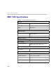
Chapter 1-Hardware Description RMX 1500 Specifications Table 1-1 Polycom RMX 1500 Specifications Physical Height 1U (4.44 cm.) Width 19” (48.26 cm.) Depth 23.6” (60 cm.) Weight Up to 12 Kg. Media Protocols Audio G.711, G. 719, G.722, G.722.1, G.729A, G.723.1, Siren14, Siren 22. Video H.261, H.263, H.264. Network Interfaces IP, ISDN, PSTN and LAN H.323, SIP, ISDN, PSTN and LAN Power Supply AC Input/ Range, BTU Voltage range: 100-240 VAC ±10%, 47-63 Hz. Maximum BTU output: 3400 per hour.
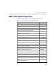
Polycom RMX 1500 Hardware Guide RMX 1500 System Capacities The following table summarizes the different system capacities.
Chapter 1-Hardware Description Table 1-2 System Functions Capacity Maximum number of Users 100 Maximum number Address Book entries 4000 Maximum number of gateway profiles 40 Maximum number of Reservations (Internal Scheduler) 2000 Table 1-3 1-4 System Functions and Capacities RMX 1500 System Resource Capacities According to Video Resolution Video Resolution Resources with MPMx HD Support CP / VSW PSTN 120 VOIP 360 ISDN 60 (128 Kbps) - 4 E1/T1 CIF H.263 60 CIF H.
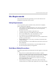
Polycom RMX 1500 Hardware Guide Site Requirements This section describes the requirements your site must meet for safe installation and operation of the system. Safety Requirements For your protection, please read these safety instructions completely before operating the equipment. • Look carefully for potential hazards in your work area: moist floors, ungrounded power cables, frayed power cords, missing safety grounds and so forth. • Locate the main circuit breaker within the room.
Chapter 1-Hardware Description • In a single rack installation, stabilizers should be attached to the rack. • In multiple rack installations, the racks should be coupled together. • Always make sure the rack is stable before extending a component from the rack. • You should extend only one component at a time - extending two or more simultaneously may cause the rack to become unstable. • Before you install the rails, determine the placement of each component in the rack.
Polycom RMX 1500 Hardware Guide Connecting the RMX 1500 to a Power Source The following restrictions apply to the conductors and connectors that may be used to ground the unit when rack mounted: • When using bare conductors, they must be coated with an appropriate antioxidant compound before crimp connections are made. Tinned, solder-plated or silver-plated connectors do not have to be prepared in this manner. • The same bolt assemblies should not secure multiple connectors.
Chapter 1-Hardware Description Connecting Cables on the RMX 1500 To connect the cables: • For the RTM-IP 1500 module: — Connect the Media cable to LAN 2 port. — Connect the Network cables to the MNG (Signaling) port & MNGB (Management Network) port. — (Optional) Connect the Shelf Management cable to the Shelf port. • For the RTM ISDN 1500 module: — Connect the E1/T1 cables to their PRI (1-4) ports.
Polycom RMX 1500 Hardware Guide The parameters in the lan.cfg file are uploaded from the USB key to the RMX’s memory and applied during the power-up sequence. System power-up sequence may take up to five minutes. During the First-time Power-up the red ERROR LED on the RMX’s front panel remains ON until both the Management and IP Network Services have been defined.
Chapter 1-Hardware Description RMX 1500 Components On the RMX 1500, components are located on both the front and rear of the MCU as listed in Table 1-4, "Polycom RMX 1500 Front Panel Description". For more information see the descriptions of the "RMX 1500 Front Panel” on page 1-10 and "RMX 1500 Rear Panel” on page 1-12. RMX 1500 Front Panel The front panel enables access to the RMX 1500 using a USB key, keyboard, mouse and VGA connection.
Polycom RMX 1500 Hardware Guide Front Panel Components USB Slot Keyboard Slot ON/OFF button Front LEDs VGA Slot Mouse slot Figure 1-2 RMX 1500 Front Panel Table 1-4 Polycom RMX 1500 Front Panel Description SLOT/Button/ LED Description USB Slot USB key connection, used for First time configuration. VGA Slot Monitor connection. Keyboard Slot Keyboard connection. Mouse Slot Mouse connection. ON/OFF Button Turn the RMX ON or OFF. READY Led Orange - RMX Starting up.
Chapter 1-Hardware Description RMX 1500 Rear Panel The RMX 1500 rear panel contains the RTM IP 1500 and optionally, the RTM ISDN 1500. In addition, the rear panel houses the power supply with fan & AC inlet, and Serial port. Power Supply with built in Fan RTM ISDN 1500 RTM IP 1500 Serial Slot RTM IP 1500 This card contains an Ethernet Switch that manages the network of the system, routes data between the cards and components of the system and provides connectivity to external IP networks.
Polycom RMX 1500 Hardware Guide LAN 1-2 Ports Signaling & Management Ports Shelf connection NA Modem Port Serial Main RS 232 Port Switch LAN3, LAN 4 and the Serial ports are only for debugging and not for customer use Standby button Figure 1-3 RMX 1500 RTM IP Rear Panel Layout The following items appear on the RMX 1500 rear panel: Table 1-5 RMX 1500 Rear Panel - RTM IP 1500 Component Description Item Description LAN 1 port Not Available (NA). LAN 2 port LAN (Media) Connection.
Chapter 1-Hardware Description Table 1-5 RMX 1500 Rear Panel - RTM IP 1500 Component Description Item Description Standby button Toggle button. Use this button to either perform Diagnostics or Software Recovery on the RMX. Short press (2 seconds) - MPMx Diagnostics. Long press - (10 seconds) Media and RTM IP 1500 Software Recovery. RTM ISDN 1500 The RTM ISDN 1500 connects directly to the built-in MPMx.
Polycom RMX 1500 Hardware Guide ISDN/PSTN Clock Source Each RTM ISDN 1500 has its own primary and secondary clock source. The first span to synchronize becomes the primary clock source and the second span to synchronize becomes the secondary clock source. This clock is used to synchronize ISDN spans only (it is not the system clock). A single clock source triggers an alarm that can be turned off by setting the appropriate flag in the system configuration.
Chapter 1-Hardware Description RMX 1500 LEDs The RMX includes LEDs located on the front panel and rear panel. In the front panel, the LEDs reflect the state of the components. The LEDs on the rear panel indicate the state of the external connections and the status of the RTM IP card. RMX 1500 Front Panel LEDs The following items appear on the RMX 1500 front panel: Table 1-7 RMX 1500 Front Panel LED’s Component LED ID LED Color Indication Front Panel ERROR Red ON - Major system error.
Polycom RMX 1500 Hardware Guide RMX 1500 Rear Panel LEDs RTM IP 1500 LEDs The following LEDs appear on the RTM IP 1500: Table 1-8 RTM IP 1500 LEDs Component LED Name LED Color Indication LAN LEDs (1-2) LNK Green ON with an active network connection, flickers with Packet activity. 1 Gb Amber ON with a 1Gb online connection, flickers with Packet activity. LNK Green ON with an active network connection, flickers with Packet activity.
Chapter 1-Hardware Description Table 1-8 RTM IP 1500 LEDs (Continued) Component LED Name LED Color Indication Modem LNK Green ON with an active network connection, flickers with activity. Amber ON when the active network is 10/100Mb, flickers with activity. ERR Red ON - Major error on RTM IP 1500. Flashes - During system startup. ACT Red ON - Packet flow to and from the MCU chassis. Flashes - During system startup. STBY Green ON - CPU & System are in a standby (OFF) mode.
Polycom RMX 1500 Hardware Guide RTM ISDN 1500 LEDS The following LEDs appear on the RTM ISDN: Table 1-9 RTM ISDN 1500 LEDs Function Name LED Name LED Color Indication PRI (1-4) LEDs LNK Green ON with an active network connection, flickers with Packet activity. 1 Gb Amber ON when 1Gb connection is online, flickers with Packet activity.
Chapter 1-Hardware Description 1-20
2 Component Installation & Replacement On the RMX 1500 you can install and replace the RTM ISDN 1500 card. For more information see, "Installing the RTM ISDN 1500 Card” on page 2-2. Before installing a parts: • Make sure you have the correct replacement part on hand. • Make sure you are using proper ESD equipment, to prevent damage to the system. Warning! • All maintenance tasks are to be performed by qualified, authorized personnel. • • Use only replacement parts supplied by your dealer.
Chapter 2- Component Installation & Replacement Installing the RTM ISDN 1500 Card Prior to adding the RTM ISDN 1500 card you must have your ISDN product license available. For more information see, RMX 1500/2000/ Getting Started Guide, "Procedure 2: Product Registration” on page 2-20. 2-2 1 Ensure that the power switch on the RMX 1500 is turned OFF (O). 2 Loosen the captive screws that fasten the card to the MCU. 3 Slide in the RTM ISDN 1500 card.
Polycom RMX 1500 Hardware Guide 5 Connect the PRI cables. 4 E1/T1 connections 6 Turn ON the RMX 1500. 7 Login on to the RMX Web Client. a Update your license. For more information see, RMX 1500/2000/ Getting Started Guide, Chapter 2, “Procedure 2: Product Registration” on page 2-20. b In the ISDN/PSTN Network Services define a New ISDN Network Service. For more information see, RMX 1500/2000/4000 Administrator’s Guide, Chapter 13, “Adding/Modifying ISDN/PSTN Network Services” on page 13-51.
Chapter 2- Component Installation & Replacement Component Replacement The RMX 1500 is designed with ease of maintenance in mind. Most components are swappable and are accessible directly via the front panel or the rear panel. The following component can be replaced when it is faulty: The RTM-IP 1500 and Power Supply are not field replaceable. • RTM ISDN 1500, see "Replacing the RTM ISDN 1500” on page 2-5. Before replacing a part: 2-4 • Make sure you have the correct replacement part on hand.
Polycom RMX 1500 Hardware Guide Replacing the RTM ISDN 1500 1 Ensure that the power switch on the RMX 1500 is turned OFF (O). 2 Remove the PRI cables. 3 Loosen the captive screws that fasten the card to the MCU. 4 Remove the RTM ISDN card and pull the RTM ISDN card out of its slot in the backplane. 5 Carefully slide the RTM ISDN card out through the rear panel. 6 Slide in the replacement RTM ISDN card into it’s slot.