ASSEMBLY IN STRUCTIO NS IMPO R T A N T Please read these instructions carefully before you start to assemble this display. Save these instructions for future reference. CD8000 v1.0.
CD8002 SHELF SUPPORT CD8005 16" SHELF (4) CD8004 32" SHELF (4) CD8001 BASE CD8003 POST CD8006 SHELF EXTENSION 10" (4) NB1979 5/32" HEX WRENCH CD8008 SIGN POST 33" No additional tools are required.
16" TOP SHELF SHELF SUPPORT SHELF EXTENSION 32" BOTTOM SHELF POST SHELF EXTENSION BASE 1. INSERT SHELF EXTENSION INTO BASE AND INSTALL OTHER SHELF EXTENSION ON OPPOSITE SIDE, INLINE WITH FIRST ONE. 2. INSERT END OF POST INTO BASE (NOTE COLLAR POSITION). SLIDE SHELF SUPPORT ONTO POST. 3. INSERT SHELF SUPPORT EXTENSION INTO SHELF SUPPORT AND INSTALL OTHER SHELF SUPPORT EXTENSION ON OPPOSITE SIDE, INLINE WITH FIRST ONE. 4. INSTALL SHELVES.
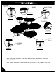
3 SCREWS (2 PL.) 2 SCREWS 1 SCREW (2 PL.) FIGURE B FIGURE A FIGURE E 2 SCREWS FIGURE F 1 SCREW (2 PL.) 3 SCREWS (2 PL.) FIGURE C FIGURE D 5. USE FOUR SET SCREWS TO ATTACH BASE (FIG. F) AND SHELF SUPPORT (FIG. E) TO POST. 6. USE 16 SET SCREWS TO HOLD SHELVES (FIG. A, B, C, & D) FIRMLY IN PLACE.
1. SLIDE SIGN POST INTO TOP OF DISPLAY. SLIDE SIGN HOLDER ONTO TOP OF SIGN POST. ONCE THE DISPLAY IS IN PLACE, ALL CASTERS MUST BE LOCKED INTO PLACE USING THE CASTER BRAKES TO PREVENT DISPLAY MOVEMENT. THE BRAKE IS ACTIVATED BY ROTATING THE LEVER FROM THE "OFF" POSITION TO THE "ON" POSITION AS SHOWN.
Do not climb, sit on, or use this product as a ladder. Injuries may occur. Do not place or install electrical items on this product. Wet conditions are typical and electrical shock may occur. Do not place this product on a slope that exceeds 3 degrees. Do not move this display after product is in place. Damage to display and injuries may occur. Lock casters (when provided) once display is in place to prevent movement. Remove all debris or obstacles from caster's path before moving.