
Data Sheet


Calibration functions UM2356
20/28 DocID031478 Rev 1
3.2 Offset calibration
Soldering the device on the customer board or adding a cover glass can introduce an offset
in the ranging distance. This part-to-part offset has to be measured and compensated
during the offset calibration.
3.2.1 Offset calibration function
A dedicated function is available for this operation:
VL53L1_PerformOffsetSimpleCalibration(&VL53L1Dev,
CalDistanceMilliMeter)
The argument of the function is the offset calibration distance in millimeters.
Note: Offset calibration has to be performed before crosstalk calibration and after RefSPAD
optimization is done (calibration done or RefSPAD parameters loaded).
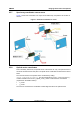
3.2.2 Offset calibration procedure
The customer has to use a calibrated chart, placed at a given distance
(
CalDistanceMilliMeter) to perform the offset calibration.
Details of the recommended setup are given in Table 5.
When the calibration function is called, the offset calibration is performed and the offset
correction is applied at the end.
3.2.3 Getting offset calibration results
The function VL53L1_GetCalibrationData() allows all calibration data to be obtained.
The returned structure VL53L1_CalibrationData_t also contains a substructure called
VL53L1_customer_nvm_managed_t which contains the main offset calibration result:
algo__part_to_part_range_offset_mm.
3.2.4 Setting offset calibration data
The customer can load the offset calibration data after the VL53L1_DataInit() and
VL53L1_StaticInit() functions are called, by using
VL53L1_SetCalibrationData().
However, it is better to call VL53L1_GetCalibrationData(), modify the parameter
described in
Section 3.2.3: Getting offset calibration results
(algo__part_to_part_range_offset_mm) and call VL53L1_SetCalibrationData().
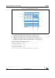
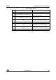
Table 5. Offset calibration set up
Chart
Chart distance
(
CalDistanceMilliMeter)
Ambient conditions
Gray target
(17 % reflectance at 940 nm)
Recommended value: 140 mm
Dark
(no IR contribution)