
Data Sheet


UM10204 All information provided in this document is subject to legal disclaimers. © NXP Semiconductors N.V. 2014. All rights reserved.
User manual Rev. 6 — 4 April 2014 7 of 64
NXP Semiconductors
UM10204
I
2
C-bus specification and user manual
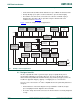
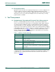
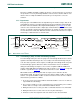
This example highlights the master-slave and receiver-transmitter relationships found on
the I
2
C-bus. Note that these relationships are not permanent, but only depend on the
direction of data transfer at that time. The transfer of data would proceed as follows:
1. Suppose microcontroller A wants to send information to microcontroller B:
– microcontroller A (master), addresses microcontroller B (slave)
– microcontroller A (master-transmitter), sends data to microcontroller B
(slave-receiver)
– microcontroller A terminates the transfer.
2. If microcontroller A wants to receive information from microcontroller B:
– microcontroller A (master) addresses microcontroller B (slave)
– microcontroller A (master-receiver) receives data from microcontroller B
(slave-transmitter)
– microcontroller A terminates the transfer.
Even in this case, the master (microcontroller A) generates the timing and terminates the
transfer.
The possibility of connecting more than one microcontroller to the I
2
C-bus means that
more than one master could try to initiate a data transfer at the same time. To avoid the
chaos that might ensue from such an event, an arbitration procedure has been developed.
This procedure relies on the wired-AND connection of all I
2
C interfaces to the I
2
C-bus.
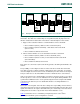
If two or more masters try to put information onto the bus, the first to produce a ‘one’ when
the other produces a ‘zero’ loses the arbitration. The clock signals during arbitration are a
synchronized combination of the clocks generated by the masters using the wired-AND
connection to the SCL line (for more detailed information concerning arbitration see
Section 3.1.8
).
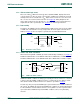
Generation of clock signals on the I
2
C-bus is always the responsibility of master devices;
each master generates its own clock signals when transferring data on the bus. Bus clock
signals from a master can only be altered when they are stretched by a slow slave device
holding down the clock line or by another master when arbitration occurs.
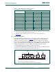
Table 2
summarizes the use of mandatory and optional portions of the I
2
C-bus
specification and which system configurations use them.
Fig 2. Example of an I
2
C-bus configuration using two microcontrollers
mbc645
SDA
SCL
MICRO -
CONTROLLER
A
STATIC
RAM OR
EEPROM
LCD
DRIVER
GATE
ARRAY
ADC
MICRO -
CONTROLLER
B